
Diagnosis of fault conditions in embedded systems

a technology of embedded systems and fault conditions, applied in the field of fault diagnosis, can solve the problems of significant “downtime”, impose a considerable cost, and limited capacity of known embedded systems to “work around”

Inactive Publication Date: 2007-06-12
NOKIA CORP
View PDF7 Cites 5 Cited by
  • Summary
  • Abstract
  • Description
  • Claims
  • Application Information

AI Technical Summary

Benefits of technology

"The present invention provides a method, system, and computer program product for diagnosing fault conditions in an embedded system with limited storage capacity. The method involves determining fault information, communicating it to a master controller, receiving diagnostic code from the master controller, and executing the diagnostic code. The system includes a processor and a communications port for data transmission and reception. The method can be used to switch to redundant circuitry or estimate the value of a faulty sensor device. The master controller can be remote from the embedded system. The technical effects of the invention include improved fault diagnosis and recovery in embedded systems with limited storage capacity."

Problems solved by technology

Known embedded systems have a limited capability to “work around” an abnormal or fault condition.
This imposes a considerable cost, and also may result in significant “downtime” for the equipment which the embedded system controls,
The cost sensitivity and size restrictions of such systems restrict the implementation of complex fault diagnosis and fault rectification applications in the system.
In particular, many embedded systems have limited Read Only Memory for storing code and Random Access Memory for use as workspace when executing such code.

Method used


Image

  • Diagnosis of fault conditions in embedded systems
  • Diagnosis of fault conditions in embedded systems
  • Diagnosis of fault conditions in embedded systems

Examples


Embodiment Construction

[0036]Where reference is made in any one or more of the accompanying drawings to steps and / or features, which have the same reference numerals, those steps and / or features have for the purposes of this description the same function(s) or operation(s), unless the contrary intention appears.

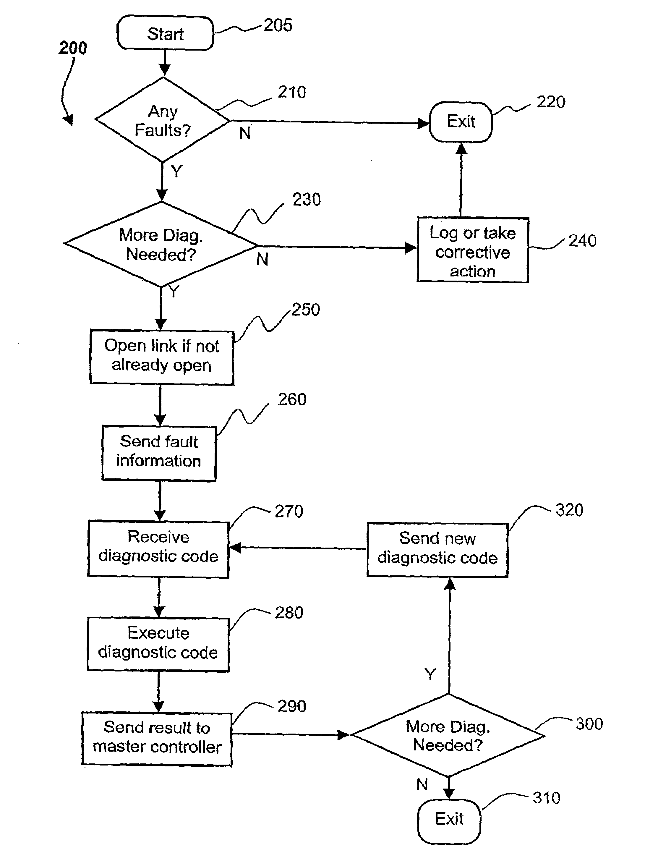
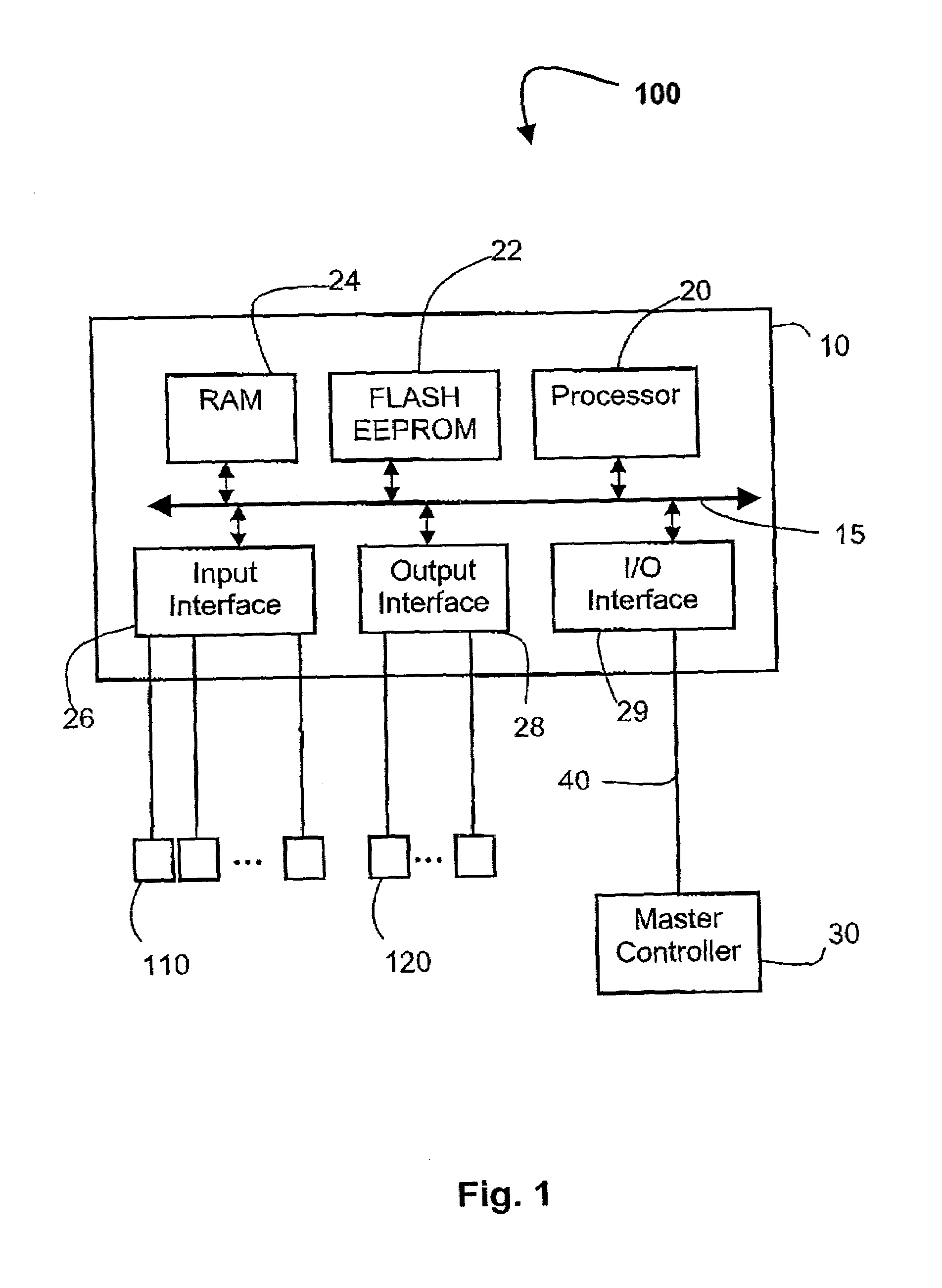
[0037]FIG. 1 shows a typical configuration for an embedded system 100. The embedded system 100 comprises a microprocessor module 10, input devices such as sensor devices 110 and output devices including actuators 120. The microprocessor module 10 communicates to and from a remote master controller 30 over a communication link 40. The communication link 40 may be a dial-up connection, a wireless radio link or a network connection, such as in an Ethernet Local Area Network (LAN) or a Wide Area Network (WAN).

[0038]The microprocessor module 10 typically includes at least one processor unit 20, random access memory (RAM) 24, a Flash electrically erasable programmable read only memory (EEPROM) 22 and inp...


PUM


Abstract

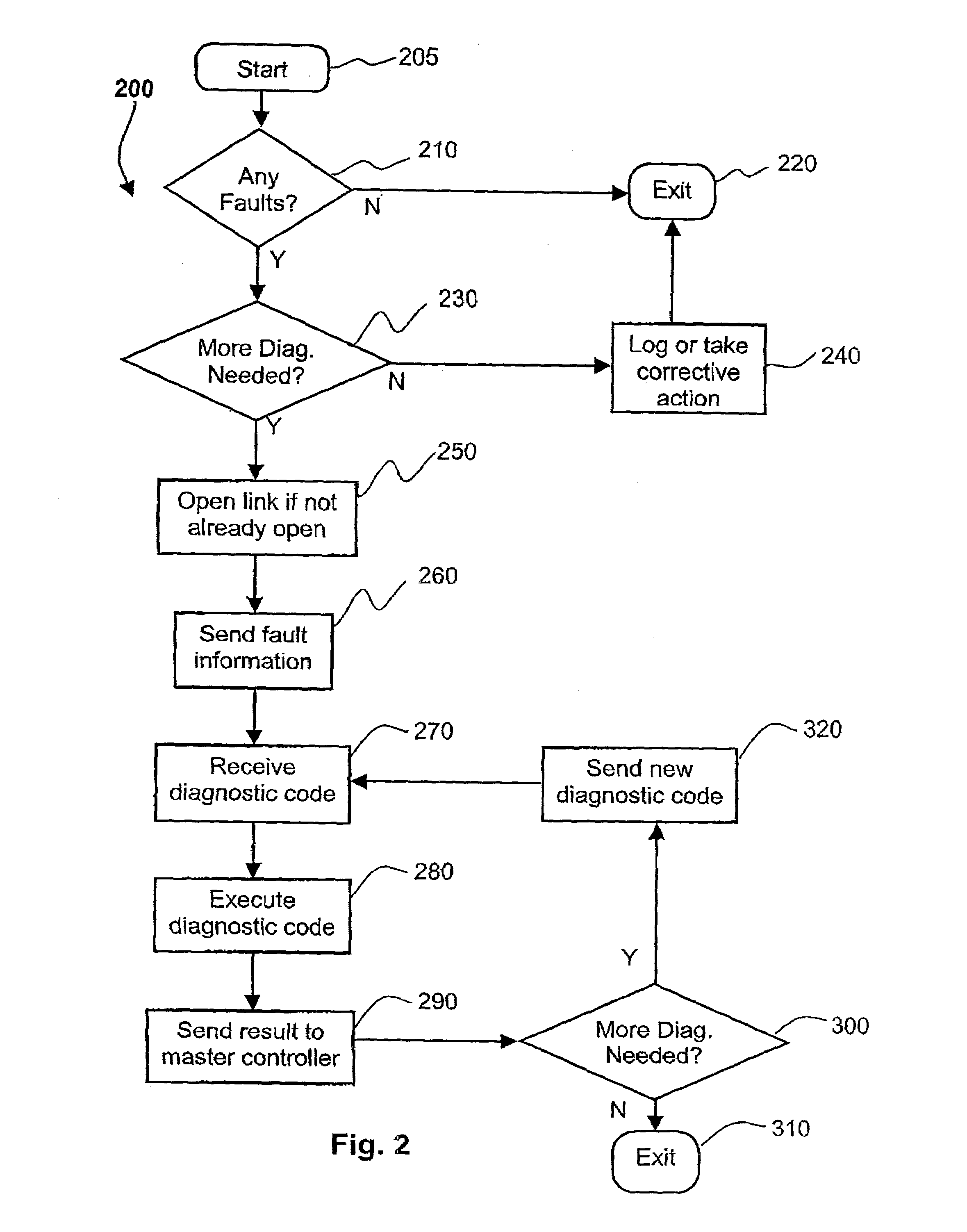
An embedded system (100) comprising a microprocessor module (10) connected to a remote master controller (30) is described, wherein diagnostic code is not loaded into the microprocessor module (10) at normal execution time, but is dynamically loaded from the remote master controller (30) when a fault is detected. The diagnostic code may be used to “work around” fault conditions, or to further diagnose the fault to a more specific level.

Description

TECHNICAL FIELD OF THE INVENTION[0001]The present invention relates generally to the field of embedded microprocessor based systems and, in particular, to fault diagnosis in such systems.BACKGROUND ART[0002]Microprocessor-based embedded systems are often used to control processes, collect data, and perform computations. They are usually hidden in equipment, and have no man-machine interface, such as a keyboard Embedded systems find applications in consumer electronics, industrial electrical equipment and in telecommunications, for example.[0003]The microprocessor of an embedded system has the capability to detecting a number of internal faults and abnormal operation of one or more of the external devices connected to it. Such devices may include a number of sensor devices and actuators. Known embedded systems have a limited capability to “work around” an abnormal or fault condition. In most instances of abnormal and fault conditions, the embedded system will fail and alarm condition...

Claims


Application Information

Patent Timeline
Patent Type & Authority Patents(United States)
IPC IPC(8): G06F11/00G06F11/25G06F11/273
CPCG06F11/2252G06F11/2736
Inventor ALI, RAFIQ
Owner NOKIA CORP
Learn More