Vehicle test system including plurality of apparatuses mutually communicable via network

a test system and plurality of apparatuses technology, applied in vehicle testing, structural/machine measurement, instruments, etc., can solve the problems of limiting the number of ecus mountable in the vehicle, increasing the weight and power consumption of the vehicle, and limiting the number of ecus for each vehicle, etc., to achieve the effect of suppressing the increase of processing load

Active Publication Date: 2010-10-07
DENSO CORP
View PDF23 Cites 28 Cited by
  • Summary
  • Abstract
  • Description
  • Claims
  • Application Information

AI Technical Summary

Benefits of technology

[0014]The present invention has been made in light of the above situations mentioned above, and has as its objec

Problems solved by technology

However, the space inside a vehicle is usually limited, thus, limiting the number of ECUs mountable in the vehicle.
Of course, increasing the number of ECUs results in an increase in the vehicle weight and power consumption.
This also limits the number

Method used


Image

  • Vehicle test system including plurality of apparatuses mutually communicable via network
  • Vehicle test system including plurality of apparatuses mutually communicable via network
  • Vehicle test system including plurality of apparatuses mutually communicable via network

Examples


second embodiment

[0116]With reference to the drawings FIGS. 9A-9B to 11A-11B, hereinafter will be described the second test system according to the second embodiment of the present invention.

[Explanation of the Configuration]

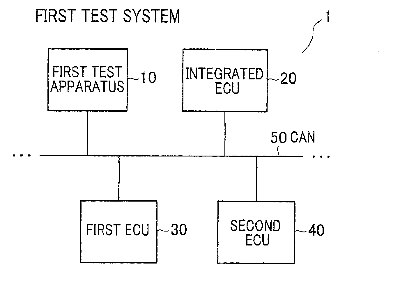
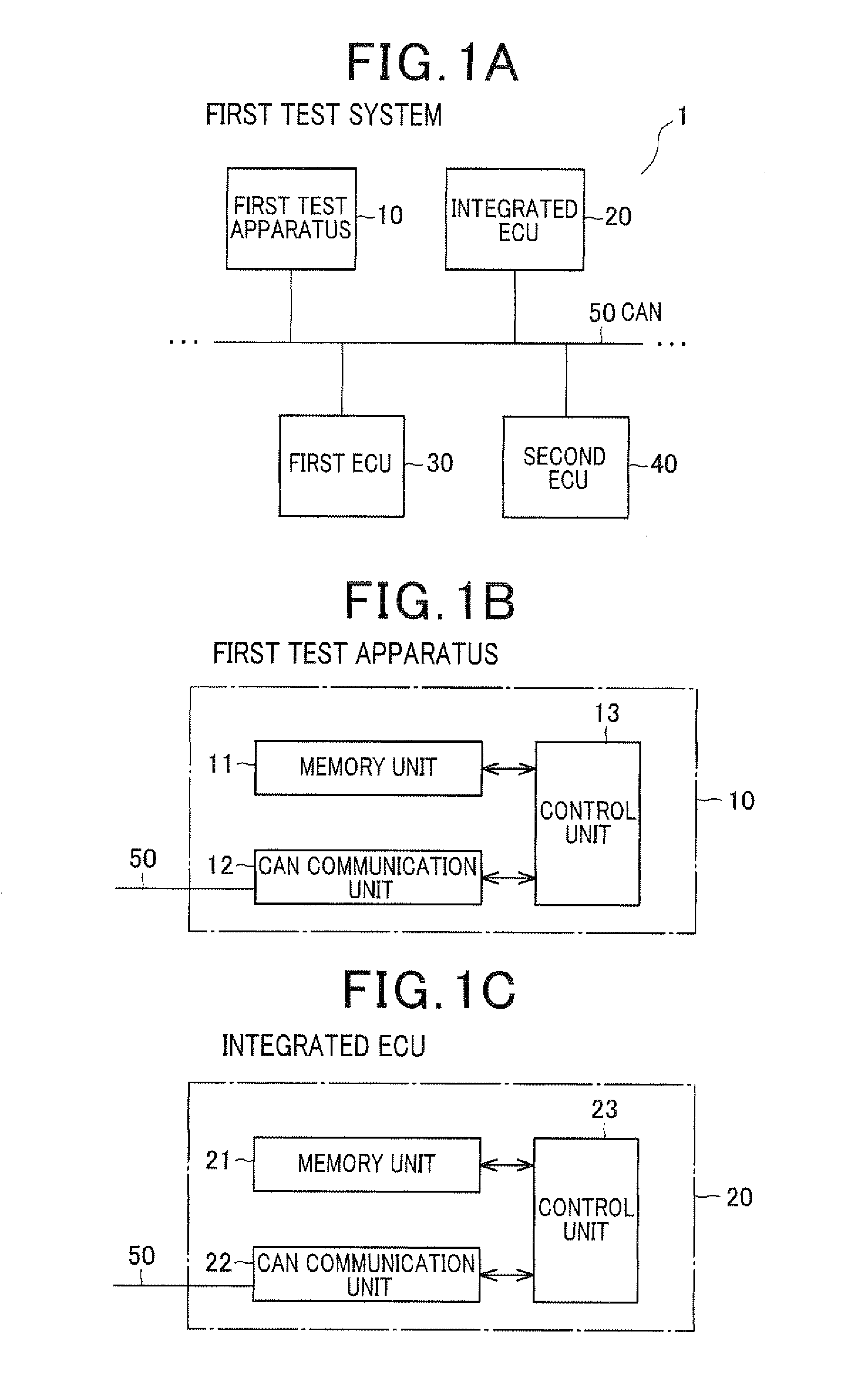
[0117]FIG. 9A illustrates a block diagram showing a configuration of the second test system 5 according to the second embodiment. The second test system 5 is mounted on the vehicle and includes the second test apparatus 60, the integrated ECU 20 as similar to the first test system according to the first embodiment, the first ECU 30 and the second ECU 40. These units are mutually connected by the CAN 50. The second test apparatus 60 can communicate with the remote center. In addition to these ECUs, the second test system 5 owns other ECU which is not shown.

Next, a configuration of the second test apparatus 60 will be described with reference to FIG. 9B. The second test apparatus 60 includes a memory unit 61, a CAN communication unit 62, a control unit 63 as similar to the first t...


PUM


Abstract

A test apparatus sends a command to an A-control module as a destination. The command includes a request to send fault information at the A-control module and a B-control module being included in an integrated ECU to the test apparatus. The A-control module reads the own diagnostic code and orders the B-control module to read the diagnostic code of the B-control module. The B-control module reads the own diagnostic code in response to the order from the A-control module. A response data generation module in the A-control module generates a fault information command based on the diagnostic codes detected by the A-control module and the B-control module and sends the command to the test apparatus.

Description

CROSS-REFERENCE TO RELATED APPLICATION[0001]This application is related to Japanese Patent Application No. 2009-93147 filed on Apr. 7, 2009, the contents of which are hereby incorporated by reference.BACKGROUND OF THE INVENTION[0002]1. Field of the Invention[0003]The present invention relates to a test system, and more particularly, a test system including a test apparatus used for detecting faults which may occur in on-vehicle devices.[0004]2. Description of the Related Art[0005]Various types of on-vehicle ECUs (Electronic Control Units) have been used to control operation of on-vehicle devices such as engines, air conditioners, and others.[0006]In order to achieve the control, an ECU is configured to communicate with various sensors and actuators. Thus, the ECU should have the capability of processing various data from and to the sensors and actuators, In some cases, a plurality of ECUs mounted on the same vehicle are electrically and communicably connected to each other via a veh...

Claims


Application Information

Patent Timeline
IPC IPC(8): G01M17/00
CPCG07C5/008G01M17/00
Inventor YAMADA, MITSUO
Owner DENSO CORP
Why Eureka
Try Eureka