
Operation microscope

Active Publication Date: 2007-06-19
KK TOPCON
View PDF13 Cites 17 Cited by
  • Summary
  • Abstract
  • Description
  • Claims
  • Application Information

AI Technical Summary

Benefits of technology

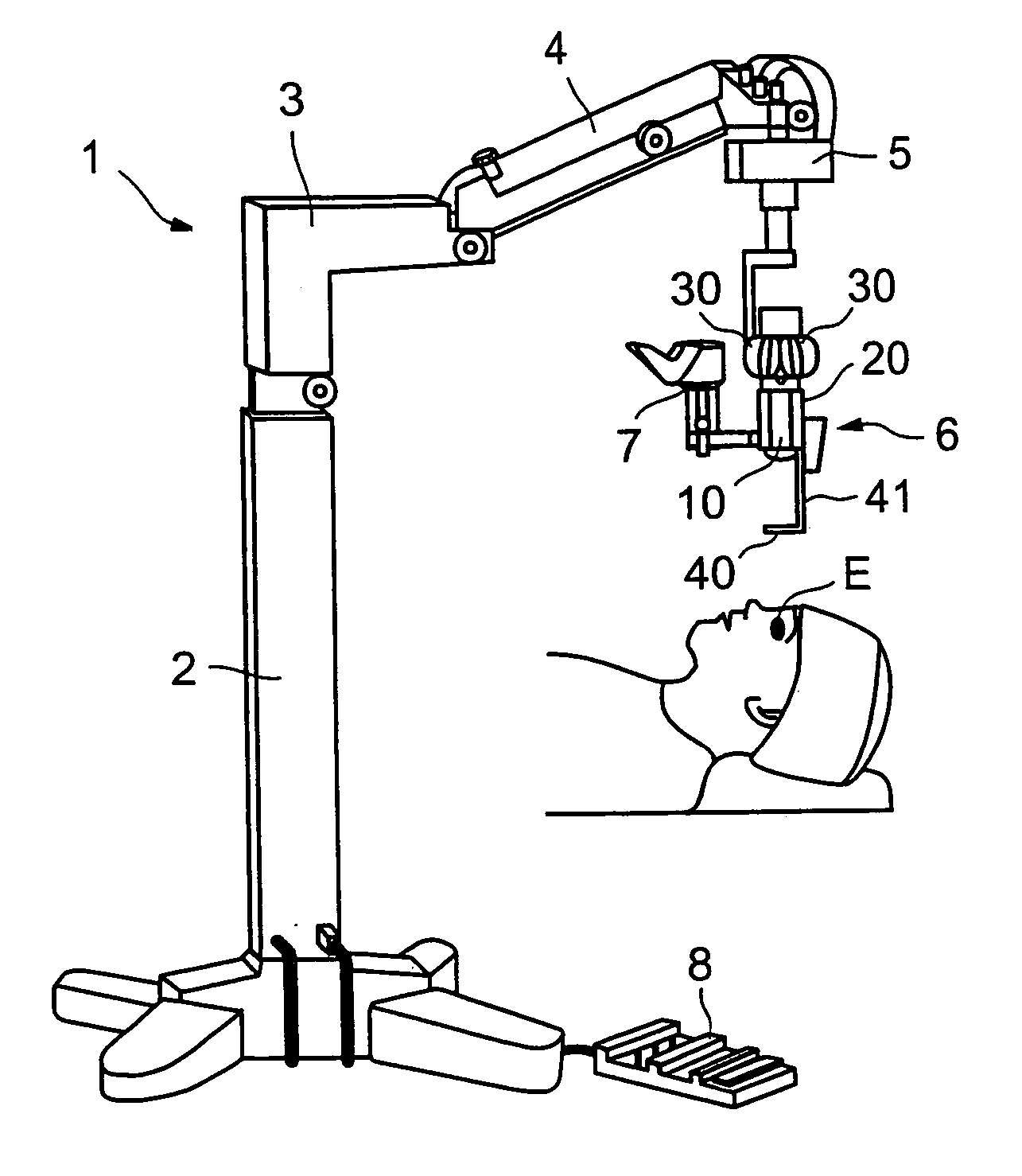
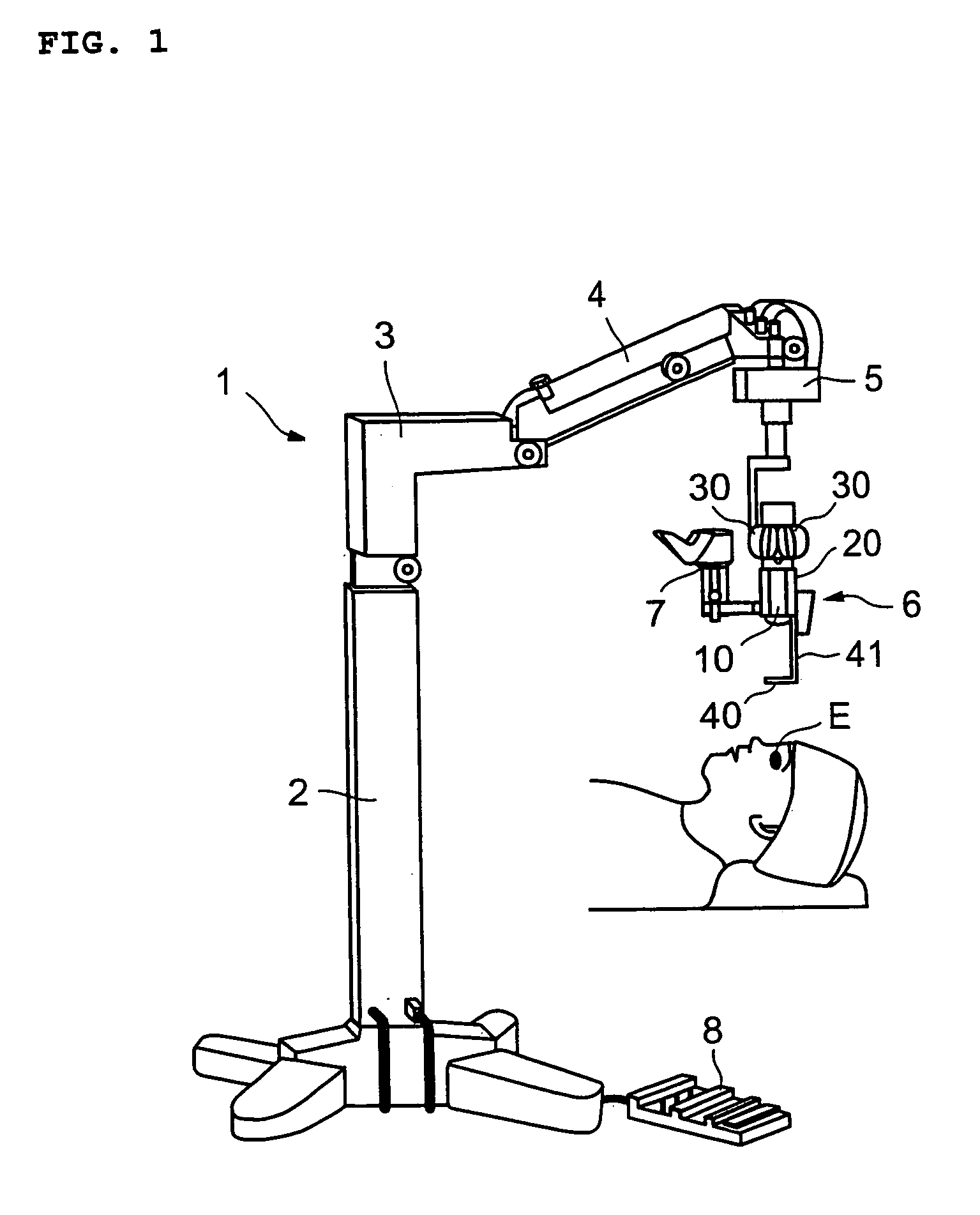
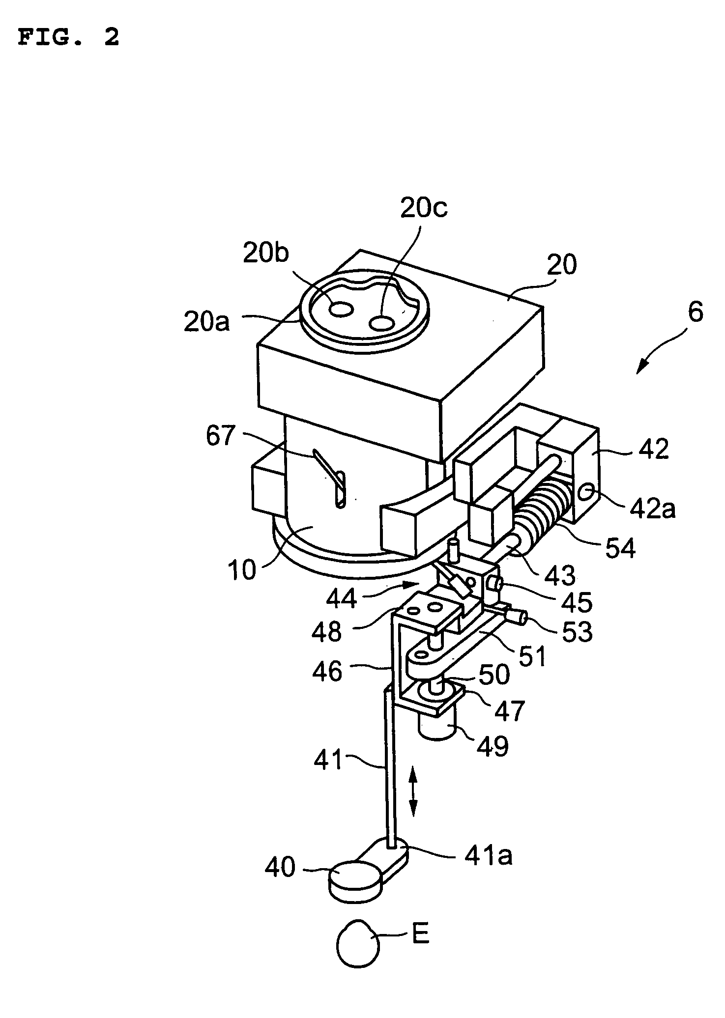
[0013]The present invention has been made in view of the circumstances described above, and has an object to provide an operation microscope which enables interlocked execution of a series of manipulations that should be performed in response to switching between methods for observing an eye to be operated, thereby enhanced in manipulability.
[0014]Further, the present invention has an object to provide an operation microscope where safety is improved by enabling the prevention of an accident where a front lens hits an eye to be operated.
[0044]Further, according to a ninth aspect of the present invention, in the operation microscope according to the second aspect of the present invention, the control means controls so that the movement of the objective lens and the front lens conducted by the moving means in a direction, in which the objective lens and the front lens approach the eye to be operated, is further prevented until the front lens and the objective lens are retracted from between the eye to be operated and the objective lens.

Problems solved by technology

An eye (eye to be operated) of a patient that is the subject of an ophthalmologic operation has an extremely minute and delicate structure, so that it is common practice to conduct the operation while observing the eye to be operated using a microscope.
Accordingly, it cannot be necessarily said that manipulability during an operation is favorable, and this becomes one factor that hinders the smooth conduct of the operation.
Consequently, there is a danger that the front lens may hit the eye to be operated.
Consequently, it is difficult to apply this technique to an operation microscope.
Consequently, it is hard to say that excellent manipulability is attained.

Method used


Image

  • Operation microscope
  • Operation microscope
  • Operation microscope

Examples


second embodiment

[0105]Now, an operation microscope of a second embodiment according to the present invention will be described. FIGS. 12A to 12C each show a schematic construction of an operator microscope 106 that is a characteristic portion of an operation microscope 101 of the FIG. 12A is an external side view of the operator microscope 106 and FIG. 12B is an external front view thereof. Also, FIG. 12C is a see-through side view showing a received mode of a front lens. Note that unless differences are specifically described, it is assumed that the operation microscope 101 has the same construction as the operation microscope 1 of the first embodiment. In particular, the operator microscope 106 is capable of being moved upwardly / downwardly by a drive apparatus that is the same as the drive apparatus 5 in the first embodiment. Also, it is of course possible to add various functions of the operation microscope 101 to be described below to the operation microscope 1 of the first embodiment.

[0106]Li...


PUM


Abstract

Provided is an operation microscope where manipulations to be performed in response to switching between methods for observing an eye to be operated are performed in an interlocked manner, thereby improving manipulability. When recognizing that a change-over switch is switched to its upper position, a control circuit controls a drive apparatus so that an operator microscope is raised, controls a drive mechanism so that an optical unit is moved to an inverter-on position, changes the turned-on position of a light source so that an illumination light flux forms a small angle with respect to an observation optical axis, and controls a solenoid so that a stereo variator is moved to be arranged on an optical path of an observation light flux.

Description

BACKGROUND OF THE INVENTION[0001]1. Field of the Invention[0002]The present invention relates to an operation microscope, and in particular to an operation microscope that is applicable to an ophthalmologic operation.[0003]2. Description of the Related Art[0004]With the recent advancement of the aging society and the like, there has been a growing demand for ophthalmologic operations than before. An eye (eye to be operated) of a patient that is the subject of an ophthalmologic operation has an extremely minute and delicate structure, so that it is common practice to conduct the operation while observing the eye to be operated using a microscope.[0005]As an example of such an operation microscope, there is known a microscope disclosed in JP 2002-350735 A (hereinafter referred to as the “known document 1”), for instance. This operation microscope has a construction where a front lens for illuminating an eye to be operated is provided between an optical system including an objective le...

Claims


Application Information

Patent Timeline
IPC IPC(8): A61B3/10A61B3/14G02B21/00G02B21/06A61B3/13G02B7/00
CPCA61B3/13G02B7/001A61B19/5223A61B90/20A01K1/0005A01K1/0047
Inventor KOGAWA, TAISAKUKITAJIMA, NOBUAKIOKAMURA, KAZUYUKI
Owner KK TOPCON
Learn More