Antenna structures and their use in wireless communication devices

a technology of antenna structure and wireless communication device, which is applied in the direction of polarised antenna unit combination, resonant antenna, independent non-interacting antenna combination, etc., to achieve good omnidirectional radiation pattern, high peak gain, and good operational performan

Inactive Publication Date: 2007-06-19
MOTOROLA SOLUTIONS INC
View PDF12 Cites 22 Cited by
  • Summary
  • Abstract
  • Description
  • Claims
  • Application Information

AI Technical Summary

Benefits of technology

[0013]The antenna structure of the present invention beneficially is suitable for use in a multi-antenna communications device such as a mobile or portable handset terminal operating at one or more high frequencies and can surprisingly be provided in a form which is compact and space saving yet providing a good operational performance. It can give a good omnidirectional radiation pattern in azimuth cut and a high peak gain by each of two or more antennae formed by the structure. It can provide good isolation between these antennae. It may be produced in a relatively cheaply and easily form.

Problems solved by technology

This is undesirable where there are practical space and size constraints on the antenna structure and on other components used in the device.

Method used


Image

  • Antenna structures and their use in wireless communication devices
  • Antenna structures and their use in wireless communication devices
  • Antenna structures and their use in wireless communication devices

Examples


Embodiment Construction

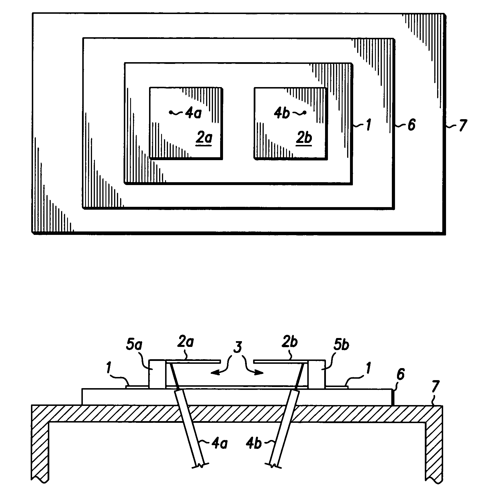
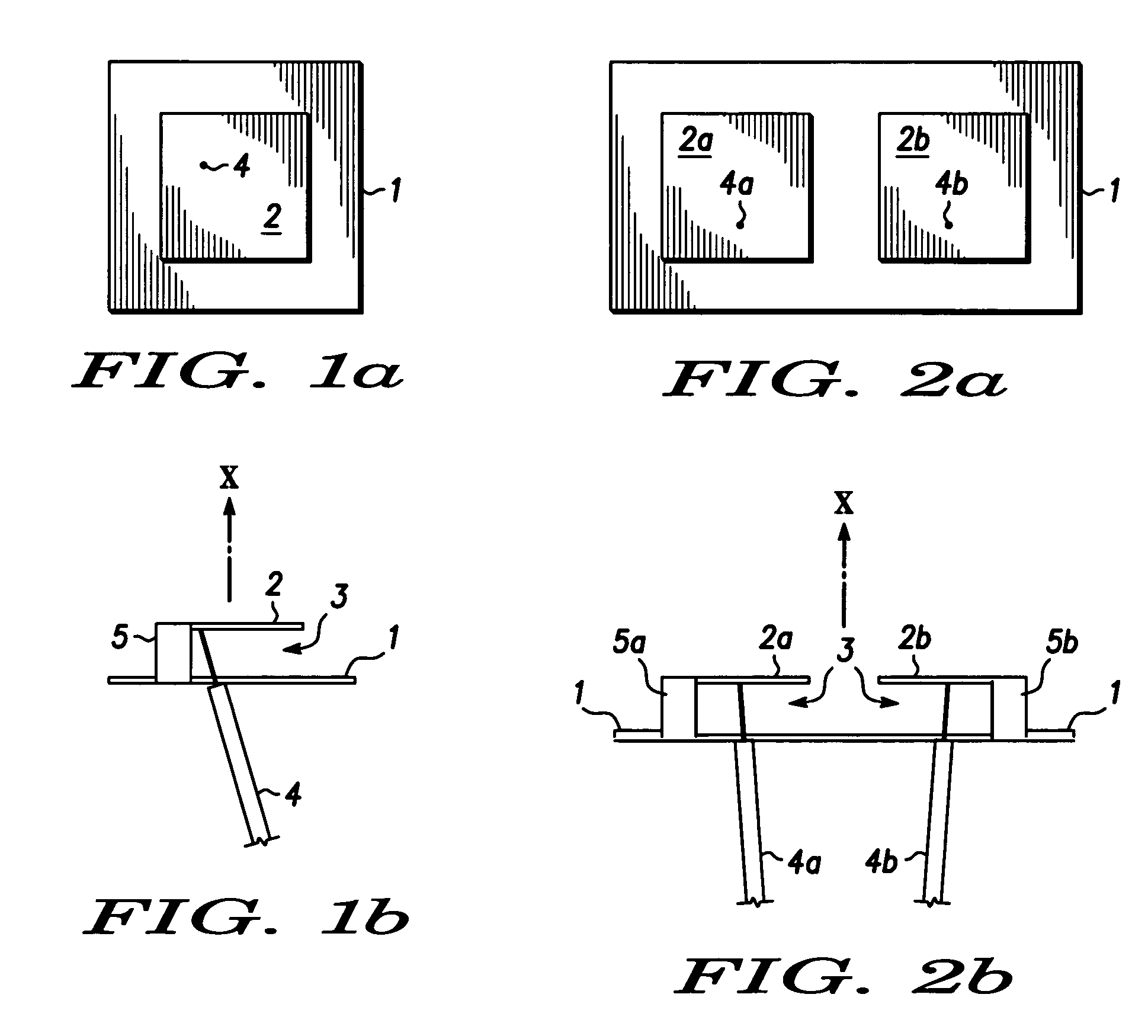
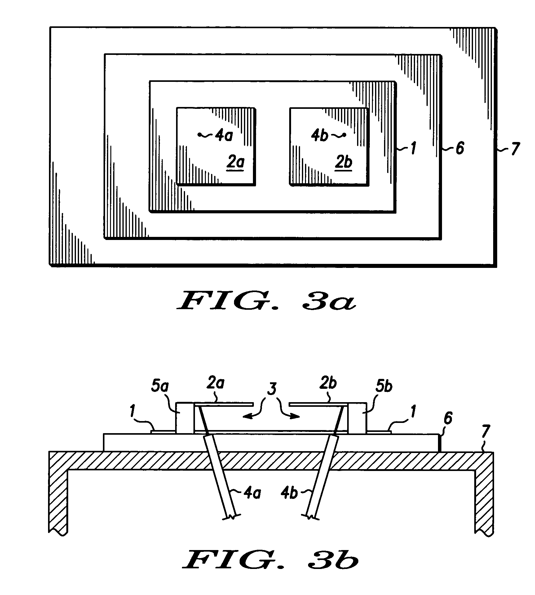
[0026]FIGS. 1a and 1b show one known form of a typical PIF antenna. FIG. 1a shows a plan view and FIG. 1b shows a side view of the same antenna. The PIF antenna includes a conducting ground plane 1, a conducting radiation element 2 parallel to the ground plane 1, a dielectric insulating material 3 (which can be air) between these and a signal feed line 4. The feed line 4 includes an inner conductor and an outer conductor. The inner conductor connects the radiation element 2 to active R.F. transceiver circuitry (not shown). The outer conductor connects the ground plane 1 to active R.F. transceiver circuitry (not shown). A grounding pin 5 electrically connects the ground plane 1 and the radiation element 2. R.F. signals produced by the transceiver circuitry are fed via the feed line 4 to the radiation element 2 and are transmitted by the radiation element 2 into the surrounding space. Similarly incoming R.F. signals are picked up by the element 2 and passed for reception to the R.F. t...


PUM


Abstract

An antenna structure for use in a wireless communication device, the structure comprising (i) a plurality of antenna portions each having a substantially planar radiating surface and (ii) a conducting ground portion; wherein the radiating surfaces of the antenna portions are substantially parallel to one another in a side-by-side relationship and are substantially parallel to part of the conducting ground portion located behind the antenna portions with respect to a direction of transmission of radiation from the antenna portions, the conducting ground portion comprising a first part galvanically connected to each of the antenna portions and, electrically coupled to the first part, a second conducting part forming at least part of a cover for a wireless communication device.

Description

RELATED APPLICATIONS[0001]This Application claims priority from Application No. PCT / EP2003 / 050389, filed Aug. 28, 2003, which claims priority from United Kingdom Application No. 0220113.5 which issued as Patent No. GB2392563 on Nov. 3, 2004.FIELD OF THE INVENTION[0002]The present invention relates to antenna structures and their use in wireless communication devices. In particular, the invention relates to antenna structures for use in portable communication devices such as handsets.BACKGROUND OF THE INVENTION[0003]Various antenna types are known for use in handheld communication devices. For example, monopole and dipole antennae, patch and so called planar inverted ‘F’ (PIF) antennae are all known for this application.[0004]Some modern wireless communication devices are designed for multi-mode use in more than one communication system. Generally, dedicated multiple antennae are required for use in each separate mode in which the device is to operate. In some cases, devices are to b...

Claims


Application Information

Patent Timeline
Patent Type & Authority Patents(United States)
IPC IPC(8): H01Q1/24H01Q5/00H01Q9/04H01Q21/28
CPCH01Q1/243H01Q9/0421H01Q21/24H01Q21/28
Inventor ELKOBI, MOTTIBEREZIN, MAKSIMNEWMAN, YONA
Owner MOTOROLA SOLUTIONS INC
Why Eureka
Try Eureka