Color filter substrate, manufacturing method thereof, displaying device, electro-optical device and electronic instrument
a technology of color filter substrate and manufacturing method, which is applied in the direction of instruments, photomechanical treatment, optics, etc., can solve the problems of reducing display brightness, increasing color absorption, and inevitably darkening of display, and achieves excellent visibility, good color contrast, and high visibility.
- Summary
- Abstract
- Description
- Claims
- Application Information
AI Technical Summary
Benefits of technology
Problems solved by technology
Method used
Image

Examples
first embodiment
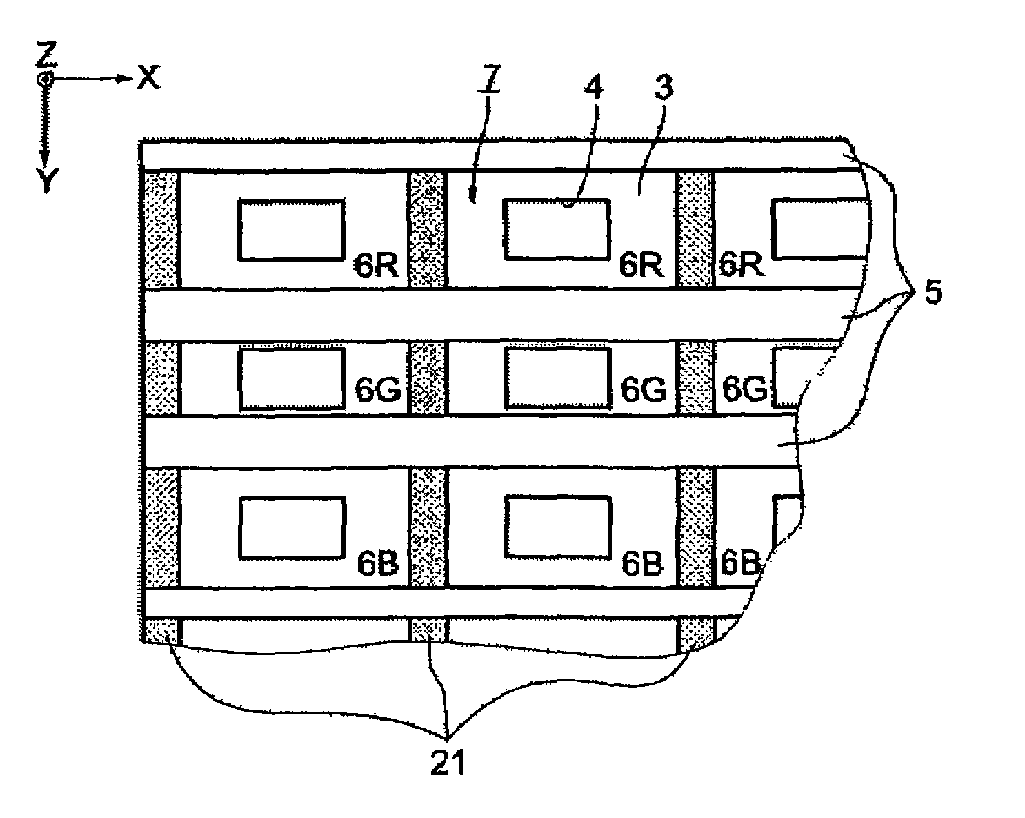
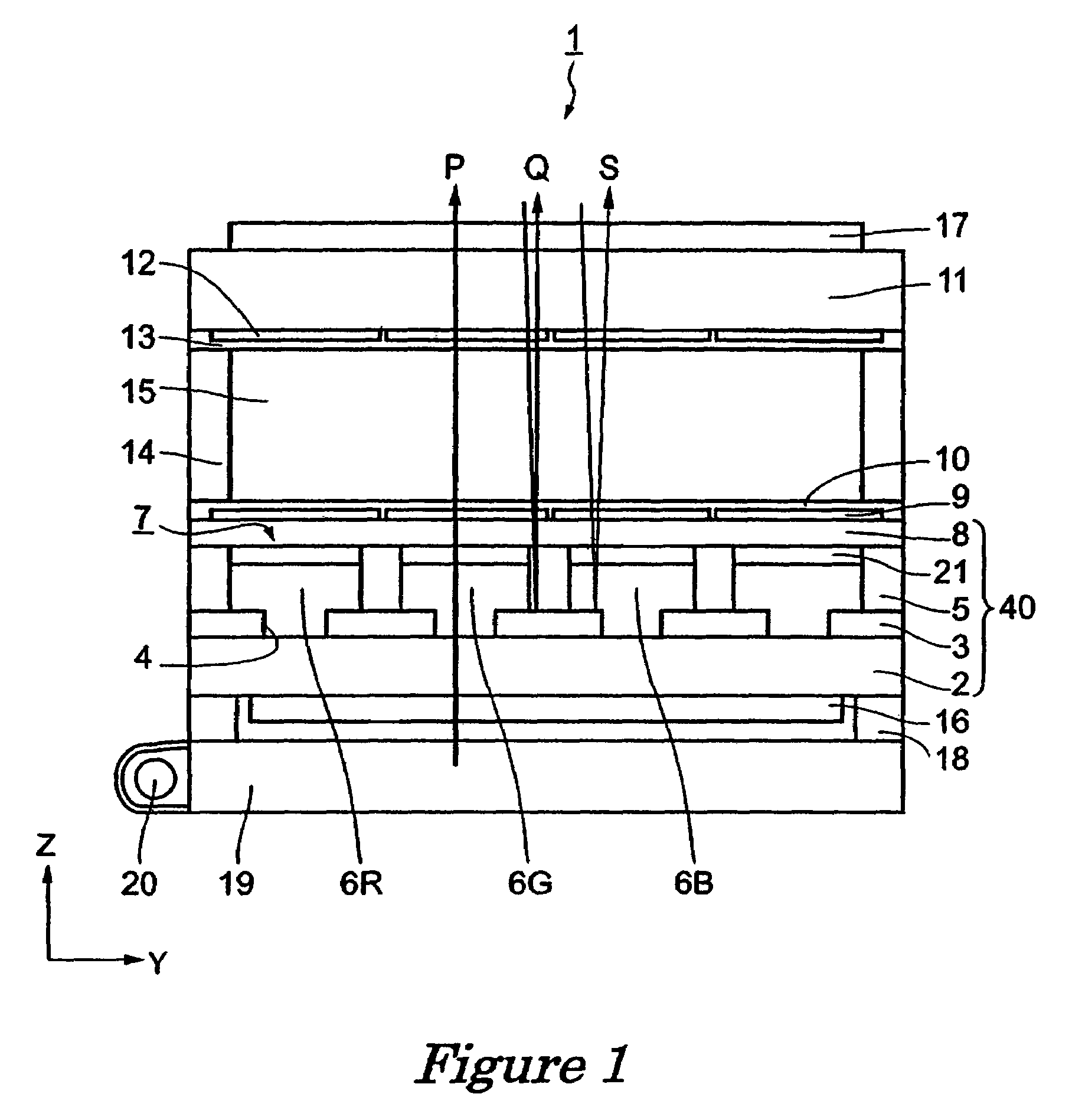
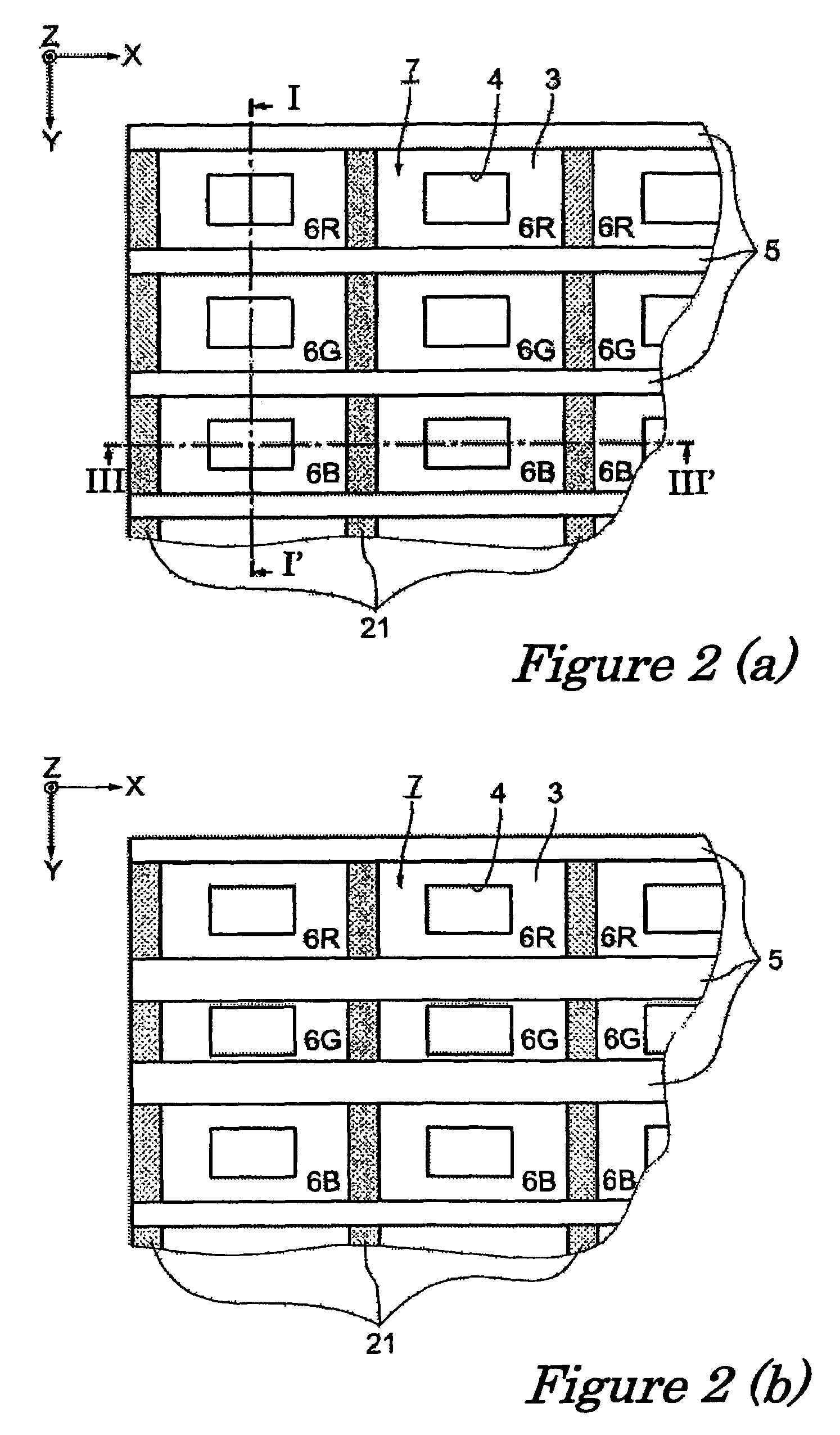
[0080]FIG. 1 shows a cross section of a semi-transmissive-reflective liquid crystal displaying device in accordance with the present invention. In the cross section, the side of a liquid crystal 15 where a light source 20 is disposed is called the back side, and the other side is called the front side. The displayed contents are normally viewed from the front side. FIGS. 2(a) and 2(b) are top views of the arrangement of the boundary layers, which are the essential part of the present invention. More specifically, FIG. 2(a) shows a top view of one example of the arrangement of boundary layers in the semi-tranmissive-reflective displaying device according the present invention while FIG. 2(b) shows a top view of another example of the arrangement of boundary layers in which green boundary layers are formed narrower than read and blue boundary layers. A plurality of light transmissive uncolored boundary layers 5, which extends along the X-axis so as to be parallel to one another, and a...
second embodiment
[0093]The liquid crystal display device in accordance with a second embodiment of the present invention will next be described. In view of the similarity between the first and second embodiments, the parts of the second embodiment that are identical to the parts of the first embodiment will be given the same reference numerals with a prime (′) as the parts of the first embodiment. Moreover, the descriptions of the parts of the second embodiment that are identical to the parts of the first embodiment may be omitted for the sake of brevity.
[0094]FIG. 4 is a cross-sectional view depicting the semi-light-transmissive reflecting liquid crystal display device 30 in accordance with the second embodiment of the present invention. As in the first embodiment, the side of the liquid crystal 15′ on which the light source 20 is disposed is referred to as the back side, and the opposite side as the front side in this cross-sectional view. Also with regard to the arrangement of the boundary layers...
third embodiment
[0137]An electro-optical device in accordance with another embodiment of the present invention will be briefly described. The electro-optical device of the present embodiment is a display device in which a color filter provided with light-transmissive uncolored boundary layers 5 is combined with an organic EL (electroluminescence) element for emitting white light. As depicted in FIG. 12, this electro-optical device 50 is composed of a color filter unit 51 and an organic EL unit 52.
[0138]The color filter unit 51 is composed of a front substrate 11″; a shared substrate 64 disposed opposite the front substrate 11″; a uncolored boundary layer 5″ formed on the front substrate 11″ side of the shared substrate 64; red, green, and blue coloring layers 6R″, 6G″, and 6B″; an uncolored boundary layer 5″; a colored boundary layer 21″; and an overcoat layer 8″ for covering the coloring layers 6R″, 6G″, and 6B″.
[0139]The organic EL unit 52 is composed of an EL substrate 55, a plurality of switchi...
PUM
| Property | Measurement | Unit |
|---|---|---|
| wave length | aaaaa | aaaaa |
| transparent | aaaaa | aaaaa |
| transparent | aaaaa | aaaaa |
Abstract
Description
Claims
Application Information
 - R&D
- Intellectual Property
- Life Sciences
- Materials
- Tech Scout
- Unparalleled Data Quality
- Higher Quality Content
- 60% Fewer Hallucinations
Browse by: Latest US Patents, China's latest patents, Technical Efficacy Thesaurus, Application Domain, Technology Topic, Popular Technical Reports.
© 2025 PatSnap. All rights reserved.Legal|Privacy policy|Modern Slavery Act Transparency Statement|Sitemap|About US| Contact US: help@patsnap.com