
Interleaved memory heat sink

a heat sink and memory technology, applied in the direction of electrical apparatus construction details, instruments, semiconductor/solid-state device details, etc., can solve the problems of reducing the possible density, stagnating airflow near the dram dimm surface, and individual servicing, i.e., individual vertical injection and ejection of each dram dimm in a dram dimm array,

Active Publication Date: 2007-06-19
ORACLE INT CORP
View PDF7 Cites 54 Cited by
  • Summary
  • Abstract
  • Description
  • Claims
  • Application Information

AI Technical Summary

Benefits of technology

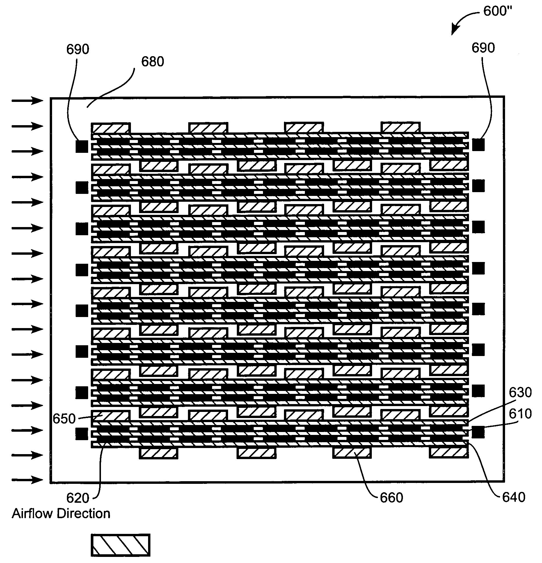
[0010]Broadly speaking, the present invention fills this need by providing an interleaved heat sink structure. A memory heat dissipation control system and a method of assembly a memory part that includes a DIMM and two heat sinks are also described.

Problems solved by technology

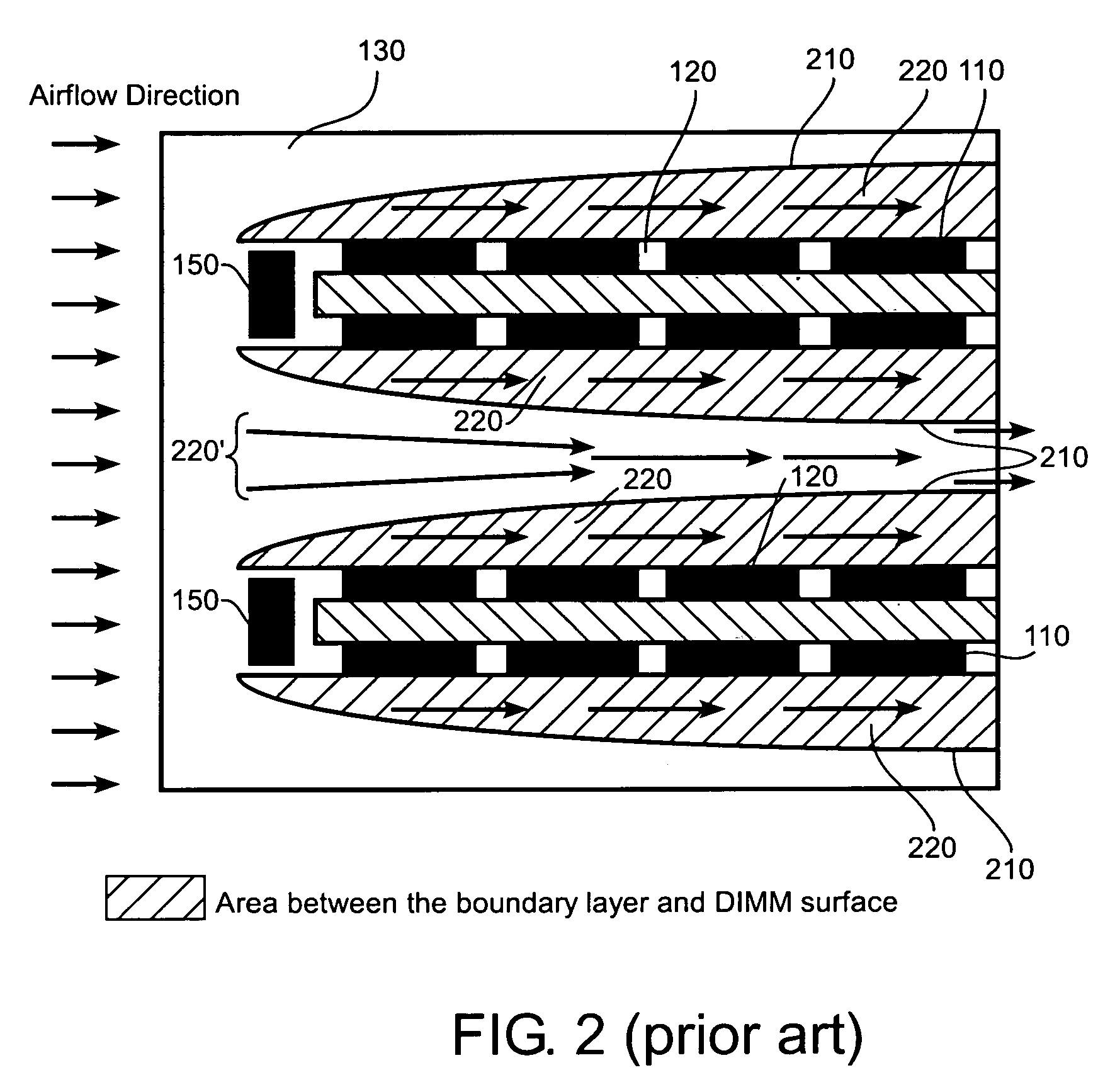
However, in a system where a DRAM DIMM array is placed on a host board in close proximity to each other, such as 12.7 mm, this creates a situation where the air must flow through narrow air channels between the DRAM DIMMs.
As a result, a boundary layer is developed around each DRAM DIMM, which results in a stagnation of airflow near the DRAM DIMM surface.
This, however, conflicts with achievable DRAM DIMM density because such a heat sink design would reduce the possible density in which DRAM DIMMs could be placed in an array since the heat sink would occupy space that could otherwise be occupied with a denser placement of DRAM DIMMs.
If the heat sinks are placed in close proximity to each other, individual servicing, i.e., the individual vertical injection and ejection, of each DRAM DIMM in a DRAM DIMM array might be jeopardized.

Method used


Image

  • Interleaved memory heat sink
  • Interleaved memory heat sink
  • Interleaved memory heat sink

Examples


Embodiment Construction

[0026]Reference is made in detail to embodiments of the invention. While the invention is described in conjunction with the embodiments, the invention is not intended to be limited by these embodiments. On the contrary, the invention is intended to cover alternatives, modifications and equivalents, which may be included within the spirit and scope of the invention as defined by the appended claims. Furthermore, in the following detailed description of the invention, numerous specific details are set forth in order to provide a thorough understanding of the invention. However, as is obvious to one ordinarily skilled in the art, the invention may be practiced without these specific details. In other instances, well-known methods, procedures, components, and circuits have not been described in detail so that aspects of the invention will not be obscured.

[0027]FIG. 3(a) is a top view of a heat sink 300 in accordance with one embodiment of the present invention. The heat sink 300 compris...


PUM


Abstract

A heat sink comprises a heat sink base and a row of heat sink extensions that are attached to one side of the heat sink base. An interleaved heat sink structure includes a first row and a second row of heat sink extensions. The first row and the second row of heat sink extensions are coupled respectively to a first and a second heat sink bases. The first and the second heat sink bases are thermally coupled to a first plurality of memory packages and a second plurality of memory packages, respectively. The first row of heat sink extensions is parallel to and at least partially interleaved with the second row of heat sink extensions. A memory heat dissipation control system and a method for assembly a memory part that includes a DIME and two heat sinks are also described.

Description

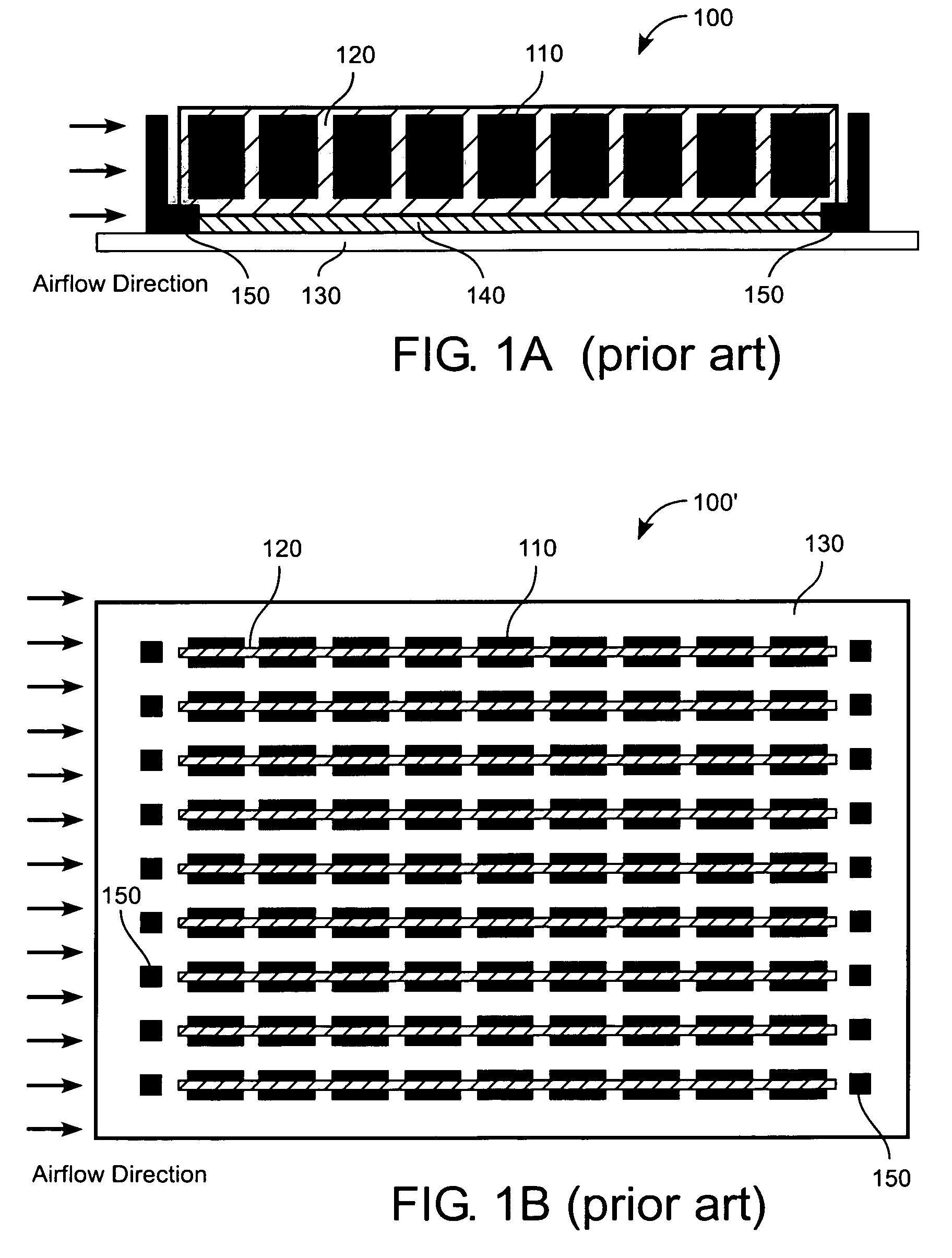
BACKGROUND OF THE INVENTION[0001]1. Field of the Invention[0002]The present invention relates generally to a heat sink, and more particularly, to an interleaved heat sink structure for dissipating heat from memory chips.[0003]2. Description of the Related Art[0004]Electronic storage medium, such as dynamic random access memory (DRAM), is frequently packaged in a way that allows for high density per unit of physical space. DRAM often dissipates heat as a part of normal operation and functions optimally within a temperature range. This is especially true given the recent proliferation of stacked, doubled sided DRAM dual inline memory modules (DIMMs) where the DRAM packages are stacked in a planar fashion, and where stacked DRAM packages are placed on both sides of a printed circuit board (PCB).[0005]FIG. 1(a) shows a side view of a conventional DRAM DIMM 100 that includes a plurality of DRAM packages 110 attached to both sides of a PCB 120. The DRAM DIMM 100 is plugged into a host boa...

Claims


Application Information

Patent Timeline
Patent Type & Authority Patents(United States)
IPC IPC(8): H05K7/00
CPCH01L23/367G06F1/185G06F1/20H01L2924/0002H01L2924/00
Inventor INGALZ, CHARLES J.
Owner ORACLE INT CORP
Learn More