Holding device for a fastening element

a technology of holding device and fastening element, which is applied in the direction of screwdrivers, metal-working devices, wrenches, etc., can solve the problems of increasing manufacturing costs, affecting the use of screws with large heads, and not being able to use known solutions for driving screws in large heads or large plain or sealing washers

Inactive Publication Date: 2007-06-26
HILTI AG
View PDF12 Cites 34 Cited by
  • Summary
  • Abstract
  • Description
  • Claims
  • Application Information

AI Technical Summary

Benefits of technology

[0026]It is advantageous when the clamping jaw is releasably connected with the clamping member. In this case, it is possible to replace a clamping jaw, which shows signs of wear, with another one, without replacing the entire clamping member. This also permits to use clamping jaws having different shapes, e.g., having circular or wedge-shaped recesses of different sizes, or formed of materials having different frictional characteristics.
[0027]Advantageously, the clamping jaw is provided with a wedge-shaped recess. With a clamping jaw having a wedge-shaped, e.g., prismatic recess, it is insured that the clamping element contacts the stem of the to-be-driven-in fastening element along two contact lines, independently of the stem diameter. This insures a reliable guidance of the stem by the clamping members.

Problems solved by technology

The drawback of the foregoing procedure consists in that, among others, the displacement length of the support part relative to the sleeve-shaped component should correspond to the length of the holding jaws.
Both solutions are associated with additional manufacturing costs.
Moreover, the known solution cannot be used for driving-in screws with large head or large plain or sealing washer.
In this case, particularly long holding jaws should be used which, in turn, would require a particularly long displacement length and, therefore, a particularly unwieldy length of the holding device.
Moreover, the production of such long holding jaws is relatively expensive, as they should insure an adequate stability during the support of the screw.
A further drawback of the known device follows from the sleeve-shaped construction of the components which provide a very limited view of a screw.
Moreover, the components have a relatively large weight which, with the arrangement of the device at the front end of the screw-driving tool, leads to an unfavorable weight distribution and, as a result, to a poor handling of the screw-driving tool.
In particularly, during the driving-in of the screw in a facade, a poor balance of a screw-driving tool is a hindrance.

Method used


Image

  • Holding device for a fastening element
  • Holding device for a fastening element
  • Holding device for a fastening element

Examples


Embodiment Construction

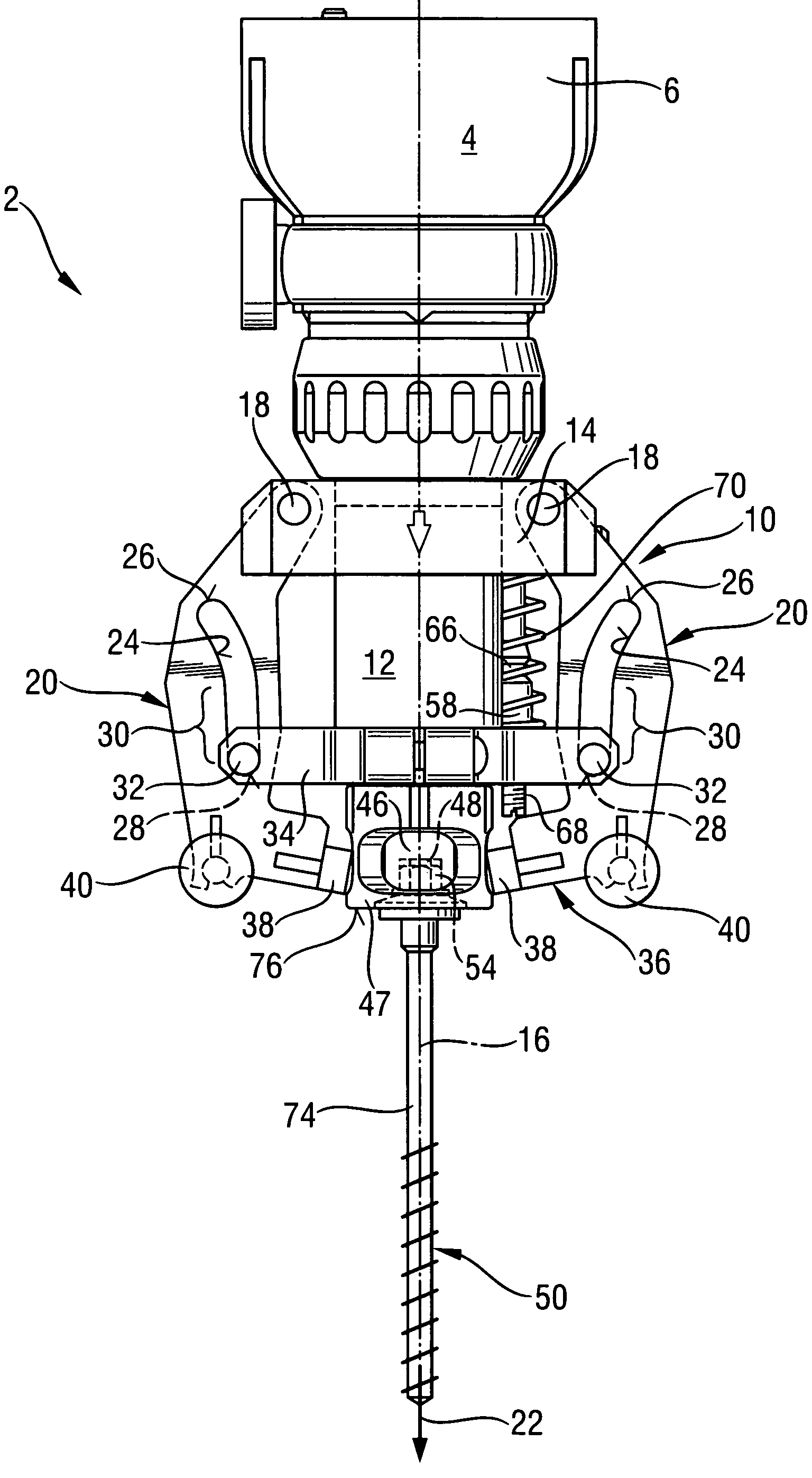
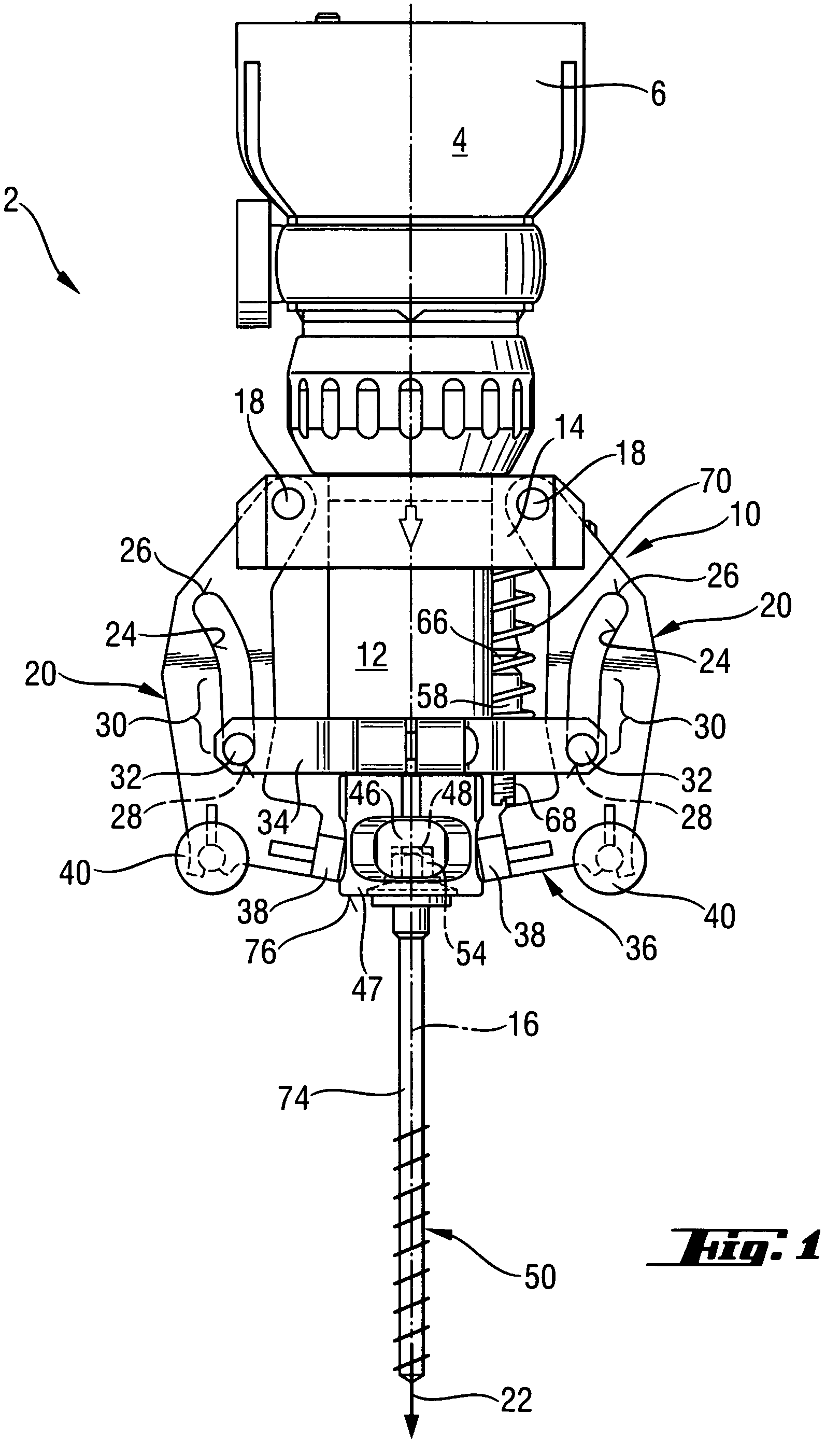
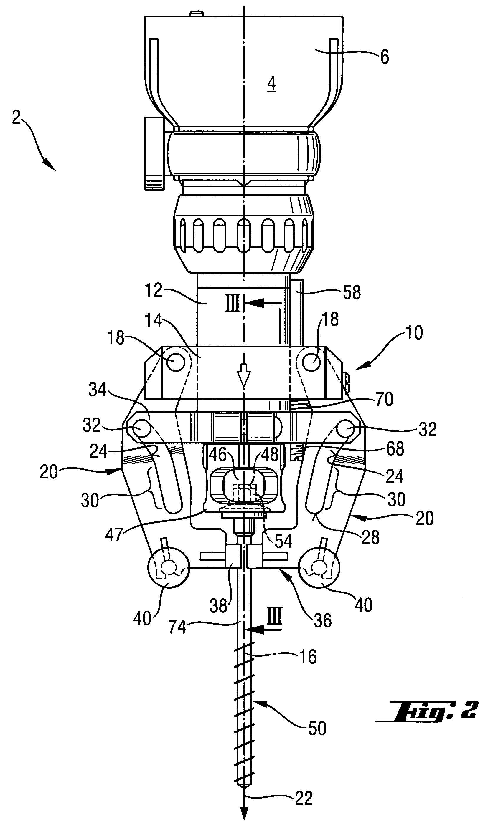
[0038]FIGS. 1 through 4 show a front portion of a screw-driving power tool 2, together with a driving gear 4 mounted in a driving gear housing 6. The driving gear 4 has a pin-on end 8 (see FIG. 3) on which a holding device 10 is mounted with aid of a support sleeve 12. On the support sleeve 12, a displacement member 14 is supported for displacement along a drive-in axis 16. The displacement member 14 is provided with two pivot supports 18, with each pivot support 18 supporting a clamping member 20 formed as a clamping arm. The clamping member 20 is supported for a pivotal movement relative to the displacement member 14 and relative to the driving gear 4 at its end facing in a direction opposite the drive-in direction 22.

[0039]Each clamping member 20 is provided with a guide recess 24 in form of an arcuate opening which is strongly curved toward one end 26. The guide recess 24 has a straight section toward the opposite end 28. A guide member 32 in form of a pin protrudes into the gui...


PUM


Abstract

A holding device for fastening elements which is securable to screw-driving power tool and includes at least two clamping members (20) which abut a stem (74) of the fastening element in a release position of the clamping members and which are displaceable upon an application of a force thereto into their release position, with the clamping members (20) having at least one contact region which forms, at least in the support position of the clamping members (20), a front stop of the holding device (10) in a drive-in direction (22) of the power tool (2).

Description

BACKGROUND OF THE INVENTION[0001]1. Field of the Invention[0002]The present invention relates to a device securable on a screw-driving power tool for holding and supporting a fastening element insertable in a tool bit of the power tool, with the holding device including at least two clamping members which abut a stem of the fastening element in a support position of the clamping members and which are displaceable upon an application of a force thereto into their release position.[0003]2. Description of the Prior Art[0004]Holding devices of the type described above provide for an automatic retention of fastening elements in a screw-driving power tool and, thereby, noticeably facilitate the driving-in process. Because the holding devices support screws radially and, thereby, prevent wobbling of the screws and the resulting damage of the surfaces the screws are driven through, the holding devices are particularly advantageous for securing elongate self-drilling screws to sensitive surf...

Claims


Application Information

Patent Timeline
Patent Type & Authority Patents(United States)
IPC IPC(8): B25B13/48B23P19/00B25B23/10
CPCB23P19/006B25B23/10
Inventor BADER, THOMAS
Owner HILTI AG
Why Eureka
Try Eureka