Misfire detector for multi-cylinder engine

a multi-cylinder engine and misfire detection technology, applied in the direction of machines/engines, electric control, ignition automatic control, etc., can solve the problems of detriment to the performance increase in the temperature of the catalyst, and the malfunction of the ignition system or fuel system, so as to and prevent the detriment or damage of the catalyst

Active Publication Date: 2007-06-26
SUZUKI MOTOR CORP
View PDF5 Cites 19 Cited by
  • Summary
  • Abstract
  • Description
  • Claims
  • Application Information

AI Technical Summary

Benefits of technology

[0023]According to the present invention, in the misfire detector for the multi-cylinder engine having the misfire detecting means to detect the misfire for each cylinder, and performing the misfire control if the frequency of the misfire detected by the misfire detecting means is more than the predetermined value, the misfire control includes (1) the fuel cut control for misfire cylinders by the fuel cut means to stop supplying the fuel to the misfiring cylinders, (2) the control to prevent the fuel feed back control and the fuel learning control and to initialize the correction values of both the fuel feed back control and the fuel learning control, and (3) the retard control to retard the ignition timing by the retard quantity set based on the extent the misfire occurs or the air-fuel ratio. Accordingly, the catalyst is not heated to high temperatures, which prevents detriment or damage of the catalyst.
[0030]Furthermore, when the misfire control is performed, executed are (1) the fuel cut control for misfire cylinders by having the fuel cut means stop supplying the fuel to the misfiring cylinders, (2) the control to prevent the fuel feed back control and the fuel learning control and to initialize the correction values of both the fuel feed back control and the fuel learning control, and (3) the vehicle speed control to limit the vehicle speed below the predetermined speed irrespective of the opening degree of the throttle. Accordingly, when misfire is detected, the driver is prevented from driving at high speed which is contrary to the misfire control for avoiding problems due to the misfires. Thereby, the catalyst is not heated to high temperatures, which prevents detriment or damage of the catalyst.

Problems solved by technology

In an engine mounted on a vehicle, there may be caused misfires due to unstable combustion of the fuel in a combustion chamber due to various factors such as lean mixture of the air-fuel ratio by driving under lean combustion, a malfunction of ignition systems or fuel systems, and a failure of components of the engine.
When misfire of the engine occurs, unburned gas flows to the catalyst in the exhaust system and burns which causes a rise in catalyst temperature that detriments the performance or damages the catalyst.
However, the air-fuel (A / F) ratio becomes lean and results in undesirable engine knocking, as shown in a time chart in FIG. 15.
This results in not only a bad influence on the engine and the catalyst but also emission of the exhaust gas in a large amount in the ambient, since the normal appropriate control for exhaust gas is not performed.

Method used


Image

  • Misfire detector for multi-cylinder engine
  • Misfire detector for multi-cylinder engine
  • Misfire detector for multi-cylinder engine

Examples


second embodiment

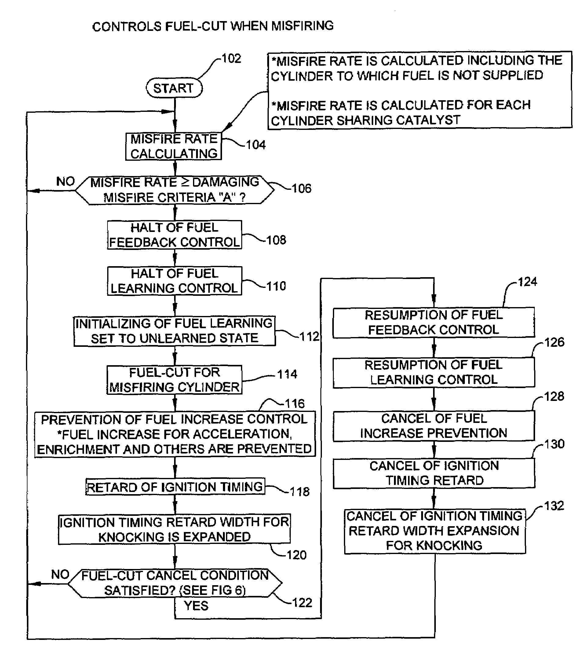
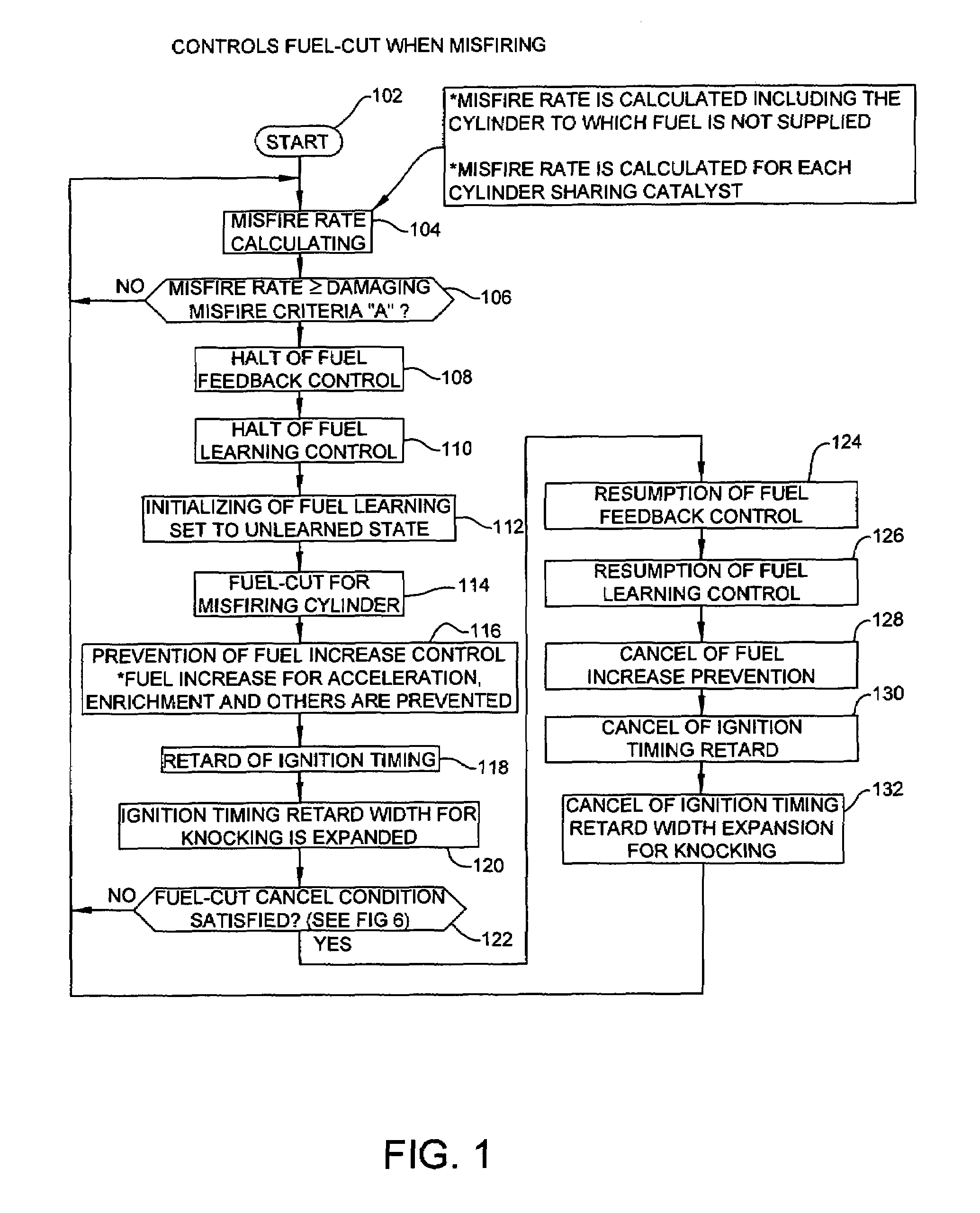
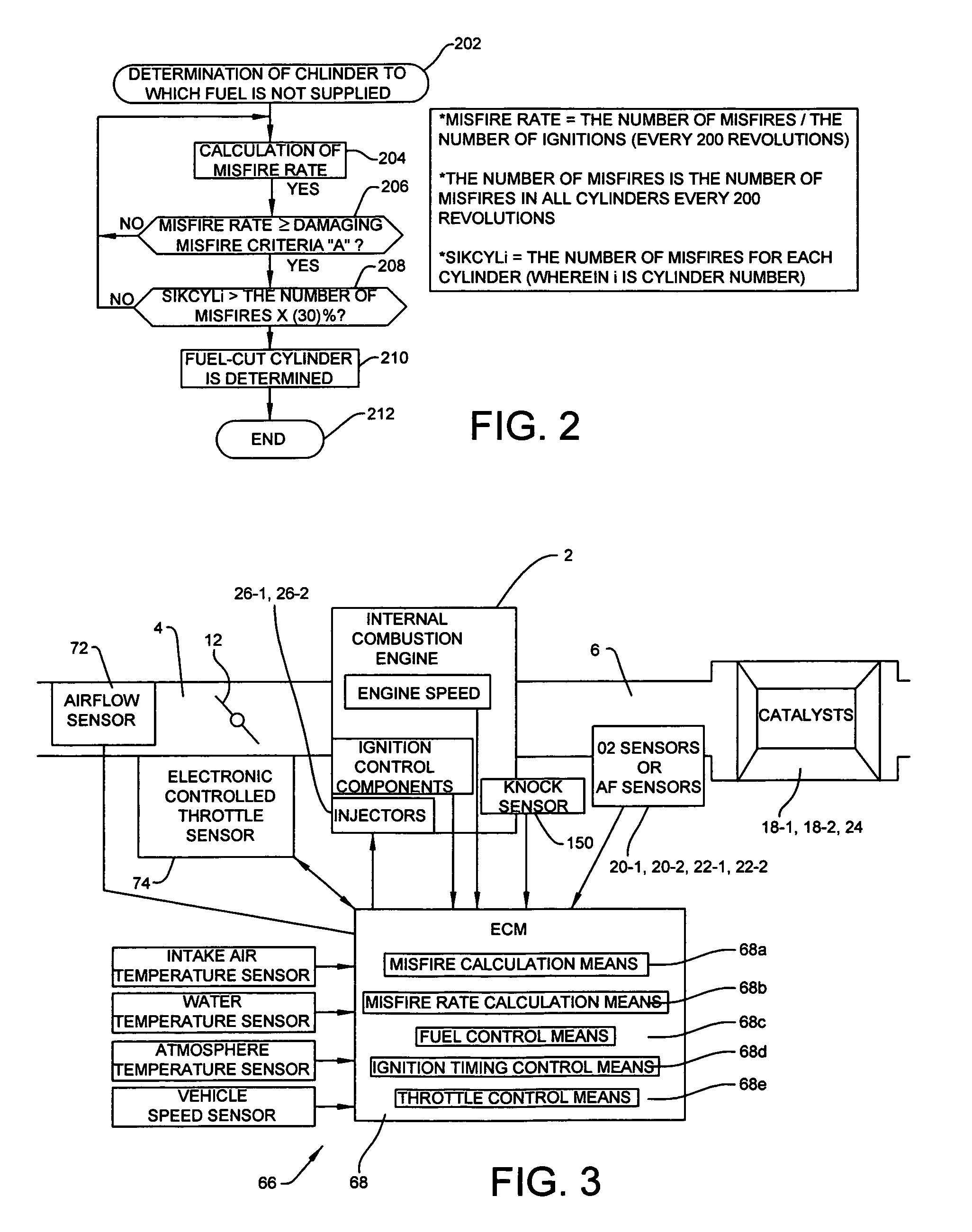
[0096]Operation of the second embodiment is explained with reference to a flowchart of FIG. 8 for throttle control of the misfire detector when misfiring. A program for the throttle control for misfire starts in step 302. The rate of misfire for each cylinder is calculated in step 304. Then a determination is made in step 306 as to whether this misfire rate is greater than or equal to the damaging misfire criteria A at which the catalyst may be damaged.

[0097]The rate of misfire is calculated for every 200 revolutions of the engine speed for each cylinder. This calculation includes the cylinder for which the fuel cut is performed. For the V-type engine, the misfire rate is calculated for each cylinder bank. Also, the misfire rate is calculated for each cylinder that shares the catalyst. The damaging misfire criteria A is calculated from a table based on the engine speed and the engine load (see FIG. 5).

[0098]In the determination in step 306 as to whether the misfire rate is greater o...

third embodiment

[0104]FIGS. 11 and 12 illustrate the present invention.

[0105]The third embodiment of the present invention is characterized in that in the misfire detector for the multi-cylinder engine, the misfire control includes (1) the fuel cut control for misfiring cylinders by having the fuel cut means stop supplying the fuel to the misfiring cylinders, (2) the control to prevent the fuel feed back control and the fuel learning control and to initialize the correction values of both the fuel feed back control and the fuel learning control, and (3) an engine speed control to limit the engine speed below a predetermined engine speed irrespective of the opening degree of the throttle. Alternatively, the third embodiment of the present invention is characterized in that in the misfire detector for the multi-cylinder engine, the misfire control includes (1) the fuel cut control for misfiring cylinders by having the fuel cut means stop supplying the fuel to the misfiring cylinders, (2) the control ...


PUM


Abstract

A misfire detector prevents catalysts from being heated to damaging high temperatures. The misfire detector for a multi-cylinder engine includes a fuel cut control to stop supplying fuel to misfiring cylinders, a control to prevent a fuel feed back control and a fuel learning control and to initialize the correction values of both the fuel feed back control and the fuel learning control, and a retard control to retard the ignition timing based on the extent that misfire occurs or the air-fuel ratio. The retard control can be replaced by a throttle opening control for misfire to limit the throttle opening angle. The retard control can also be replaced by an engine or vehicle speed control to limit the engine or vehicle speed below a predetermined engine or vehicle speed, respectively, irrespective of the throttle position.

Description

FIELD OF THE INVENTION[0001]This invention relates to misfire detectors for a multi-cylinder engine, and more particularly to a misfire detector for the multi-cylinder engine to prevent a catalyst from being heated to high temperatures and avoid detriment or damage of the catalyst.BACKGROUND OF THE INVENTION[0002]In an engine mounted on a vehicle, there may be caused misfires due to unstable combustion of the fuel in a combustion chamber due to various factors such as lean mixture of the air-fuel ratio by driving under lean combustion, a malfunction of ignition systems or fuel systems, and a failure of components of the engine. When misfire of the engine occurs, unburned gas flows to the catalyst in the exhaust system and burns which causes a rise in catalyst temperature that detriments the performance or damages the catalyst. For this reason, some engines are provided with misfire detectors to detect the misfire and control the fuel.[0003]Examples of prior detectors are disclosed i...

Claims


Application Information

Patent Timeline
Patent Type & Authority Patents(United States)
IPC IPC(8): F02P5/15F02D41/14
CPCG01M15/11F02D37/02F02D41/1498F02D41/1488F02D41/2454F02D2200/1015
Inventor TOYODA, KATSUHIKO
Owner SUZUKI MOTOR CORP
Why Eureka
Try Eureka