
High frequency heating apparatus

a heating apparatus and high frequency technology, applied in the direction of heating types, heating stoves or ranges, cleaning using liquids, etc., can solve the problems of difficult cleaning of adhered soil, troublesome cleaning of the inside of the heating chamber, and generating smoke in high frequency heating. achieve the effect of easy cleaning work

Active Publication Date: 2007-06-26
PANASONIC CORP
View PDF14 Cites 4 Cited by
  • Summary
  • Abstract
  • Description
  • Claims
  • Application Information

AI Technical Summary

Benefits of technology

[0007]The invention has been made in view of the circumstances. An object is to provide a high frequency heating apparatus in which steam used for heating an object to be heated is used for cleaning the inside of a heating chamber and this cleaning work can be done easily.

Problems solved by technology

Such adhered soil causes not only a problem in keeping the inside of the heating chamber hygienic but also a factor that generates smoke in high frequency heating.
However, cleaning the inside of the heating chamber is bothersome work, and the adhered soil is hard to be cleaned.
In this case, a sufficient wipe is needed to cause the cleaning work to be harder.
In addition, when cleaning is performed by the high temperature burning function, it is often difficult to remove the adhered soil completely even though a part of the soil is decomposed to remove odors, which inevitably depends on manual work in the end.
However, when the inside of the heating chamber of the high frequency heating apparatus is cleaned by this cleaning method, effort is needed to put water in a heatproof container and to place it in the heating chamber every time when cleaning, and the heating apparatus has to be monitored until steam is filled, which is not usable.
However, all of the heating apparatus generate steam used for heating the object to be heated, not for cleaning the heating chamber.
Therefore, there is no high frequency heating apparatus with steam generation function having an automatic cleaning function programmed for cleaning the heating chamber.
In other words, the usability in cleaning is not excellent.
Consequently, a problem is arisen to cause a dirty environment where mold is easily propagated.
Particularly, in the configuration in which the vaporizing part for generating steam is embedded in the inaccessible portion under the heating chamber, in addition to the problem, there is a problem that it is hard to do the work to clean the periphery of the heating chamber.

Method used


Image

  • High frequency heating apparatus
  • High frequency heating apparatus
  • High frequency heating apparatus

Examples


Embodiment Construction

[0038]Hereafter, a preferred embodiment of a high frequency heating apparatus in the invention will be described in detail with reference to the drawings.

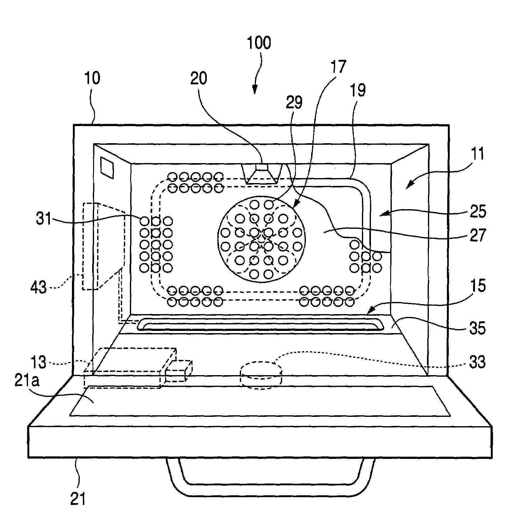
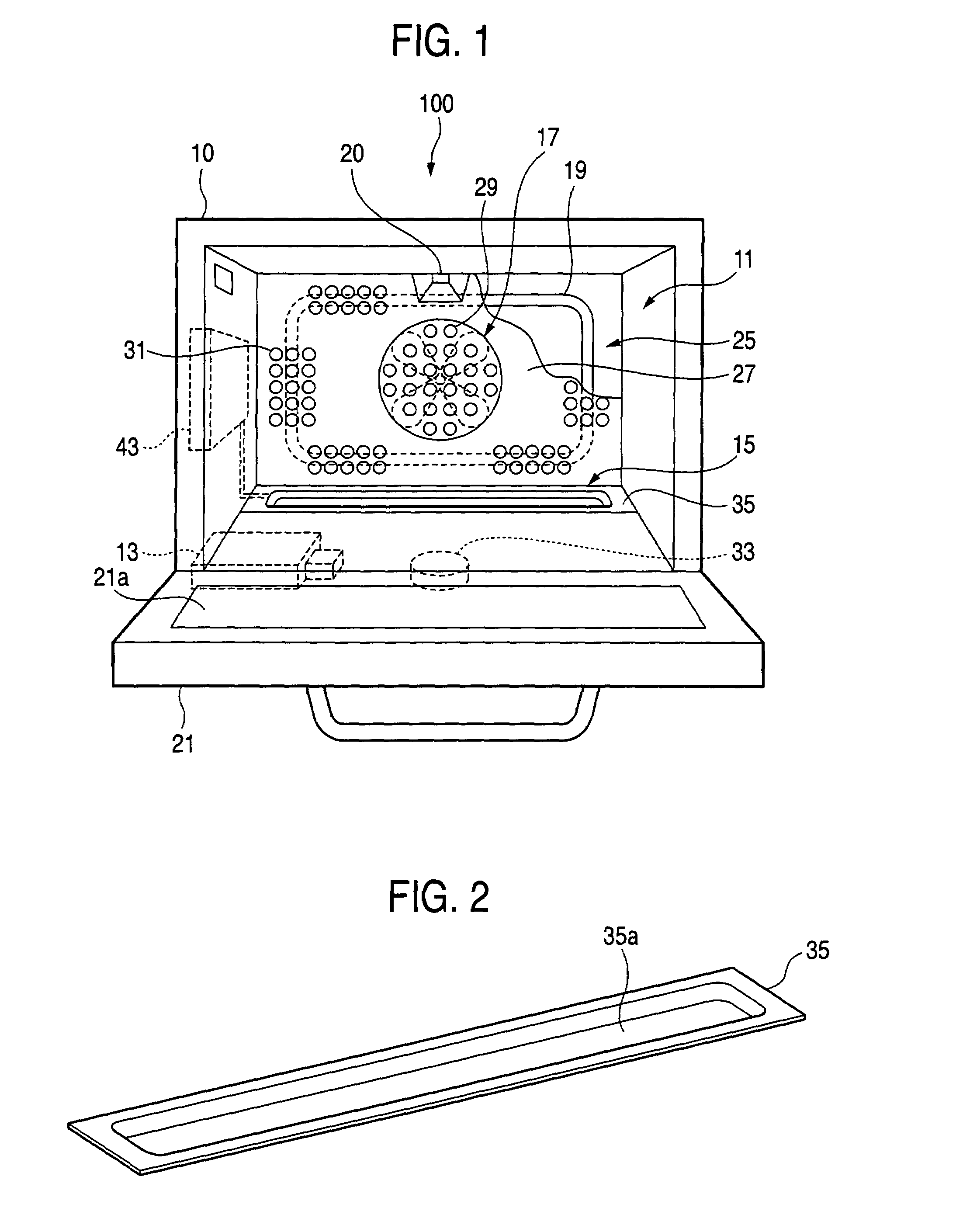
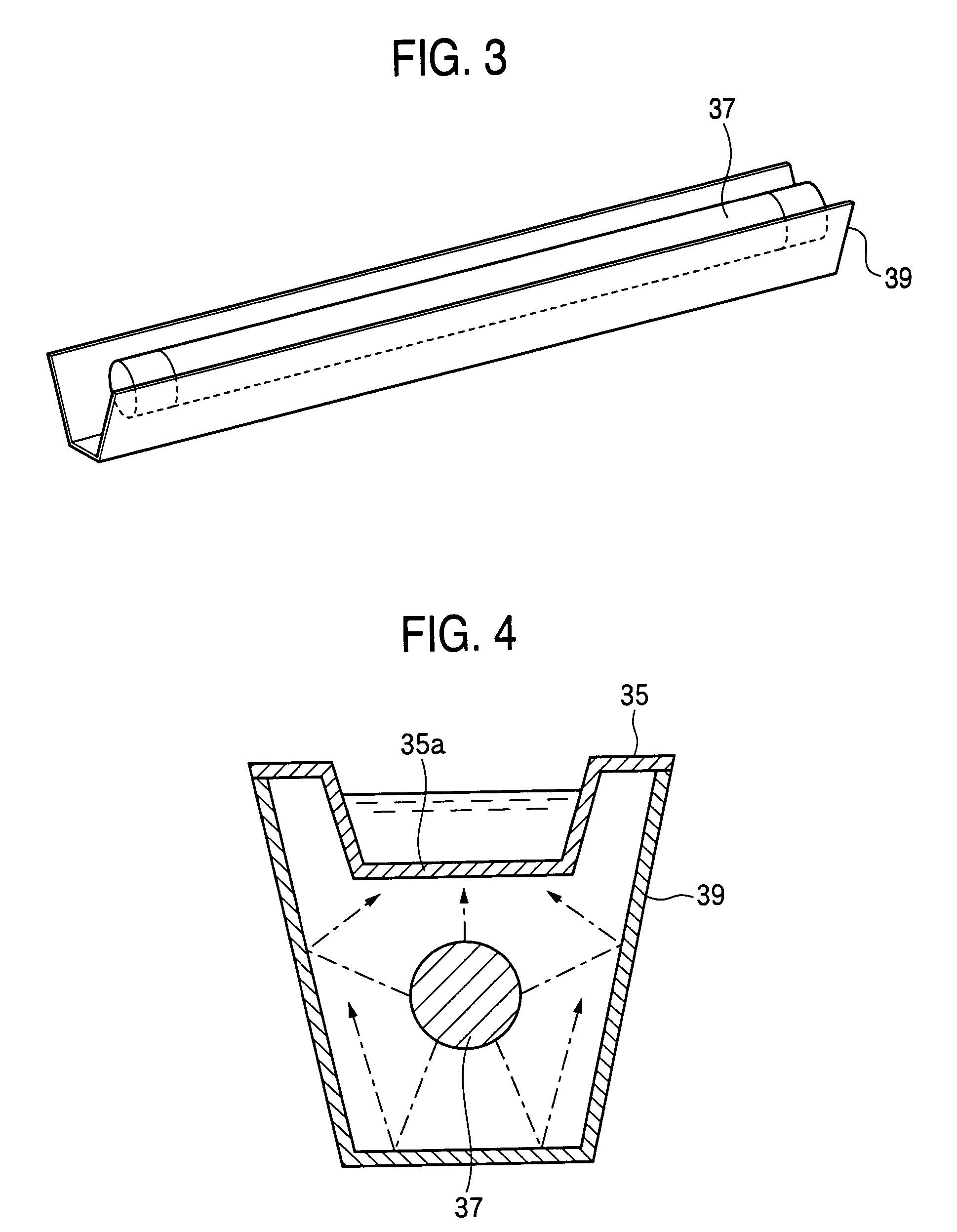
[0039]FIG. 1 is a front view illustrating a high frequency heating apparatus in the invention in which its door is opened. FIG. 2 is a perspective view illustrating an evaporating dish of a steam generating part for use in the apparatus. FIG. 3 is a perspective view illustrating an evaporating dish heater and a reflector of the steam generating part. FIG. 4 is a cross sectional view illustrating the steam generating part.

[0040]First, the basic configuration of a high frequency heating apparatus 100 in the invention will be described.

[0041]This high frequency heating apparatus with steam generation function 100 is a cooking appliance in which at least any one of a high frequency (microwave) and steam is supplied into a heating chamber 11 for accommodating an object to be heated and the object to be heated is heat-treated. The appara...


PUM


Abstract

Cleaning according to an evaporating dish cleaning mode or heating chamber cleaning mode is implemented based on a signal inputted by the control part. In the heating chamber cleaning mode, condensation is generated on the inner surface of the heating chamber 11 by steam, and the soil adhered to the inner surface of the heating chamber 11 is allowed to float to be in a state of removing it easily. In the evaporating dish cleaning mode, a cleaning liquid made of citric acid solution is pumped into an evaporating dish 35, it is heated to a predetermined temperature, and it is left therein. Therefore, calcium and magnesium deposited on the evaporating dish 35 are allowed in a state of removing them easily.

Description

BACKGROUND OF THE INVENTION[0001]The present invention relates to a high frequency heating apparatus in which an object to be heated is heat-treated with the combination of high frequency and steam, and the inside of a heating chamber soiled by the heat treatment is cleaned.[0002]In a high frequency heating apparatus for heat-treating an object to be heated by high frequency, there are a single function type of performing only high frequency heating and a multi-function type added with an oven function. However, in these pieces of the high frequency heating apparatus, juice or leavings of the object to be heated are sometimes adhered to the inside of a heating chamber for accommodating and heat-treating the object to be heated during heat treatment. When they are left as they are, adherents and burnt deposits are generated to soil the inside of the heating chamber. Such adhered soil causes not only a problem in keeping the inside of the heating chamber hygienic but also a factor tha...

Claims


Application Information

Patent Timeline
Patent Type & Authority Patents(United States)
IPC IPC(8): B08B3/10H05B11/00F24C7/02F24C14/00H05B6/68
CPCF24C14/00H05B6/6405H05B6/6479H05B6/66
Inventor KANZAKI, KOUJIHAYAKAWA, YUJI
Owner PANASONIC CORP
Learn More