Method and apparatus for anchoring laparoscopic instruments

a technology for laparoscopic instruments and anchoring devices, applied in the field of improved anchors, can solve the problems of requiring insertion of screw threads, requiring relatively traumatic twisting, and expensive fabrication of cannulas, and achieves the effect of low profile, facilitating low insertion force placement and removal

Inactive Publication Date: 2007-06-26
COVIDIEN AG
View PDF40 Cites 93 Cited by
  • Summary
  • Abstract
  • Description
  • Claims
  • Application Information

AI Technical Summary

Benefits of technology

[0008]The present invention is an improvement over the prior art in that it provides a universal balloon anchor which may be secured to the outside of a laparoscopic instrument and inflated to anchor the instrument in place within a puncture opening. The balloon is configured so as to have a low profile generally contiguous with the outside surface of the instrument to facilitate its low insertion force placement and removal, without significant trauma to the tissue defining a small laparoscopic opening.

Problems solved by technology

The screw threads also must be twisted into place and are relatively traumatic.
Blood emitting from the puncture opening often intrudes between the disk and the tissue so as to destroy the integrity of the anchor during surgery.
Such cannula are expensive to fabricate and must be especially configured to match the instrument with which they are used.

Method used


Image

  • Method and apparatus for anchoring laparoscopic instruments
  • Method and apparatus for anchoring laparoscopic instruments
  • Method and apparatus for anchoring laparoscopic instruments

Examples


first embodiment

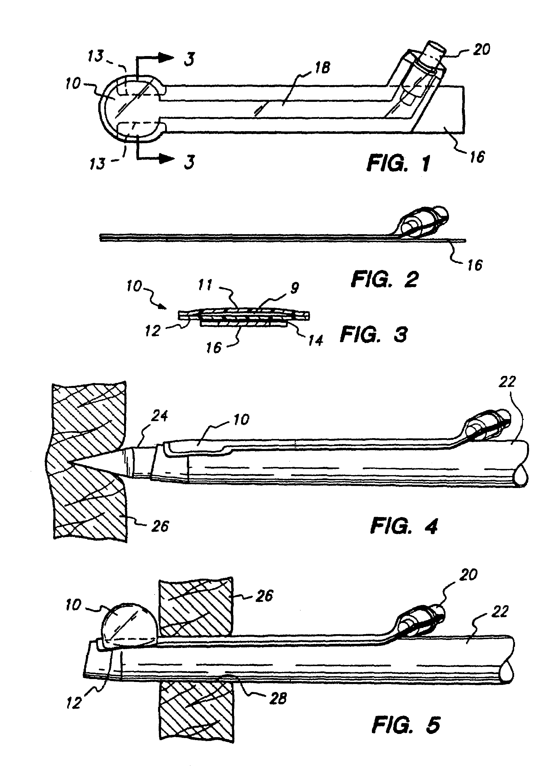
[0064]As shown in FIGS. 1–3, this embodiment comprises an elastomeric balloon 10 having a first film layer 11 of elastic or semi-elastic material, and a second film layer 12 of elastic, semi-elastic or inelastic material. Second film layer 12 is ideally very flexible so that it can easily confirm to the outside surface of an instrument such as a trocar sheath. Preferably, first film layer 11 and second film layer 12 are made of material suitable for medical applications having a good strength to thickness ratio. Thinner materials facilitate lower deflated profiles and thus lower incision insertion forces. First film layer 11 can be made of urethane or other appropriate film. A semi-elastic PS-8010 polyurethane film, referred to as PS-8010, manufactured by Deerfield Urethane of Deerfield, Mass. is suitable. Second film layer 12 is preferably a flexible inelastic material, such as polyester. A suitable material is Rexham 705517 manufactured by Rexham Industrial, Inc. of Matthews, N.C....

second embodiment

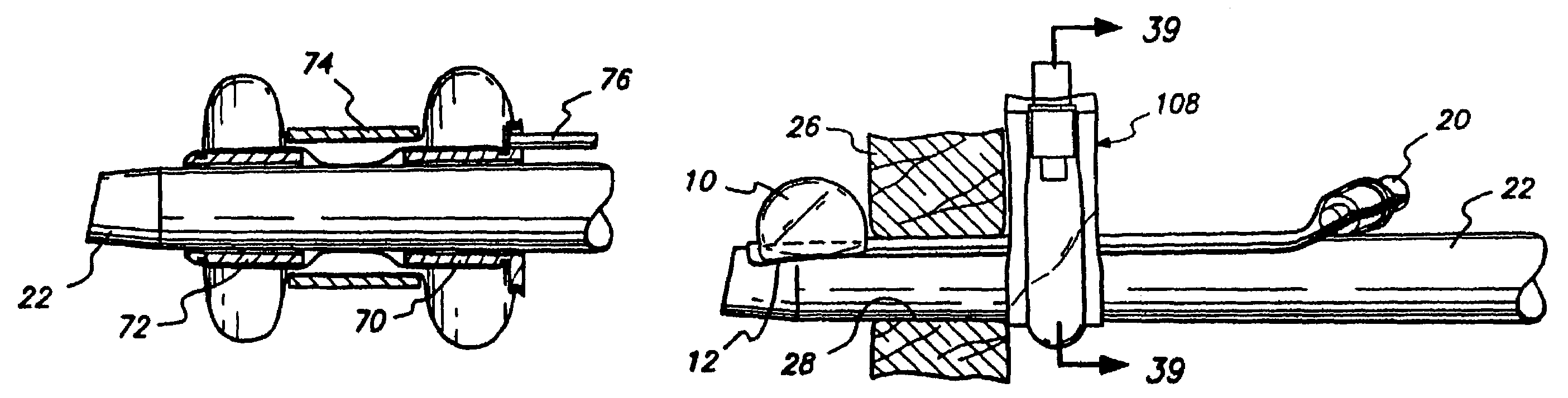
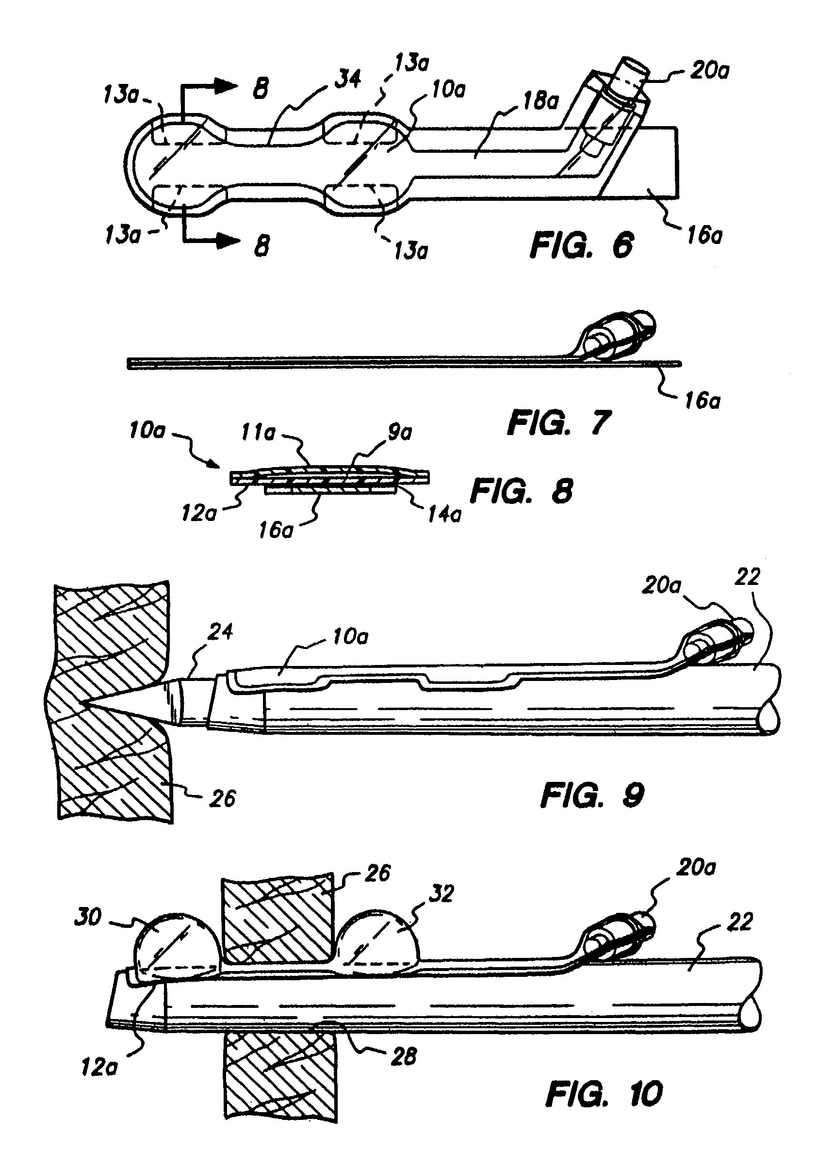
[0069]This embodiment is illustrated in FIGS. 6–10 and is similar to the first embodiment, with the exception that the balloon 10a is of an elongate hourglass-shaped configuration. Parts of the second embodiment corresponding to those of the first embodiment are designated by like numerals followed by the letter a, as follows: elastic balloon 10a; first layer 11a; second layer 12a; chamber 9a; adhesive cut-away portions 13a; contact adhesive 14a; shielding strip 16a; inflation tube 18a; and check valve or stop cock 20a.

[0070]The second embodiment balloon is applied and used in the same way as that of the first embodiment. As seen in FIG. 9, the balloon is adhered to the outside surface of a trocar sheath 22 so as to extend longitudinally of the sheath. The hourglass shape of the balloon 10a provides distal and proximal portions 30 and 32, respectively. Upon extension of the sheath 22 through the tissue as shown in FIG. 10, these portions are disposed to either side of the tissue 26...

third embodiment

[0072]As shown in FIGS. 11–15, the third embodiment is similar to that of the first embodiment, with the exception that the balloon, designated 10b, is a closed elastomeric envelope having top and bottom surfaces; and the backing strip is a patch 36 adhered to and extending over the balloon. The patch 36 is provided with contact adhesive 38 to either side of the balloon 10b. A removable paper or plastic shielding strip 16b extends across the balloon 10b and over the adhesive 38. Inflation tube 18b for the third embodiment is contiguous with the balloon 10b and also adhered beneath the patch 36. Contact adhesive 38 on the patch 36 is disposed to either side of the tube 18b and covered by the removable shielding strip 16b. A check valve or stop cock 20b is secured in the proximal end of the inflation tube 18b.

[0073]In use, the shielding strip 16b is removed from the adhesive 38 and the balloon assembly is secured directly to the outside surface of the instrument with which it is used...


PUM


Abstract

A balloon anchor provides for the anchoring of a surgical instrument, such as conventional trocar sheath, within a puncture opening formed by a trocar. When used on a trocar sheath, the anchor is secured to the smooth outer surface of the sheath for extension through the puncture opening as the trocar within the sheath forms the opening. Adhesive or mechanical means are provided to secure the balloon the instrument. No modification to the structure of the instrument is required. Once in place within the opening, the balloon is inflated to the interior of the tissue to anchor the instrument in place. Certain embodiments also provide for inflation of the balloon within and/or to the exterior of the opening.

Description

CROSS-REFERENCE TO RELATED APPLICATIONS[0001]The present application is a continuation of and claims the benefit of priority to U.S. patent application Ser. No. 08 / 447,794 filed on May 23, 1995 now U.S. Pat. No. 6,524,283, which is a Divisional Application of and claims the benefit of priority to application Ser. No. 08 / 320,042 now U.S. Pat. No. 5,697,946 filed on Oct. 7, 1994, the entire contents of which are incorporated herein by reference.BACKGROUND OF THE INVENTION[0002]The present invention relates to an improved anchor for securing laparoscopic instruments within puncture opening during surgery. In its more specific aspects, the invention is concerned with a balloon anchor adapted to be secured to the outside surface of virtually any laparoscopic instrument, without the necessity of modifying the structure of the instrument.[0003]Laparoscopic surgery provides a minimally invasive approach to a wide variety of surgical procedures in, for example, the abdominal and thoracic cav...

Claims


Application Information

Patent Timeline
Patent Type & Authority Patents(United States)
IPC IPC(8): A61M5/00A61B17/34A61M25/04
CPCA61B17/3421A61M25/04A61B2017/3486A61B2017/3492A61M2025/0233
Inventor HOPPER, PHILLIP K.KOVAC, TIM J.ROSCHAK, EDMUND J.ENG, WILSON
Owner COVIDIEN AG
Why Eureka
Try Eureka