Sphenoid sinus stent

a sphenoid sinus and stent technology, applied in the field of stents, can solve the problems of severe headache, increased pressure in the sinuses, runny nose, etc., and achieve the effect of easy passage back through the ostium

Inactive Publication Date: 2007-06-26
MICROMEDICS
View PDF7 Cites 166 Cited by
  • Summary
  • Abstract
  • Description
  • Claims
  • Application Information

AI Technical Summary

Benefits of technology

[0016]At a later time, the stent may be removed by again using a forceps to grasp the proximal end of the tube and pull...

Problems solved by technology

The resulting congestion interferes with breathing and often causes a “runny nose”.
Since the sinuses act as resonance chambers, this changes the sound of the voice and may also cause such a pressure increase within the sinuses that severe headaches result.
However, due to infection...

Method used


Image

  • Sphenoid sinus stent
  • Sphenoid sinus stent
  • Sphenoid sinus stent

Examples


Embodiment Construction

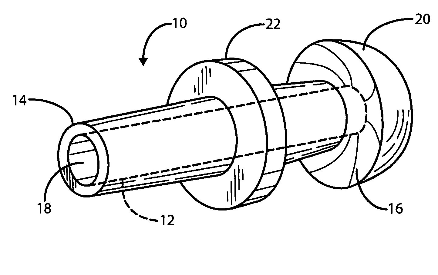
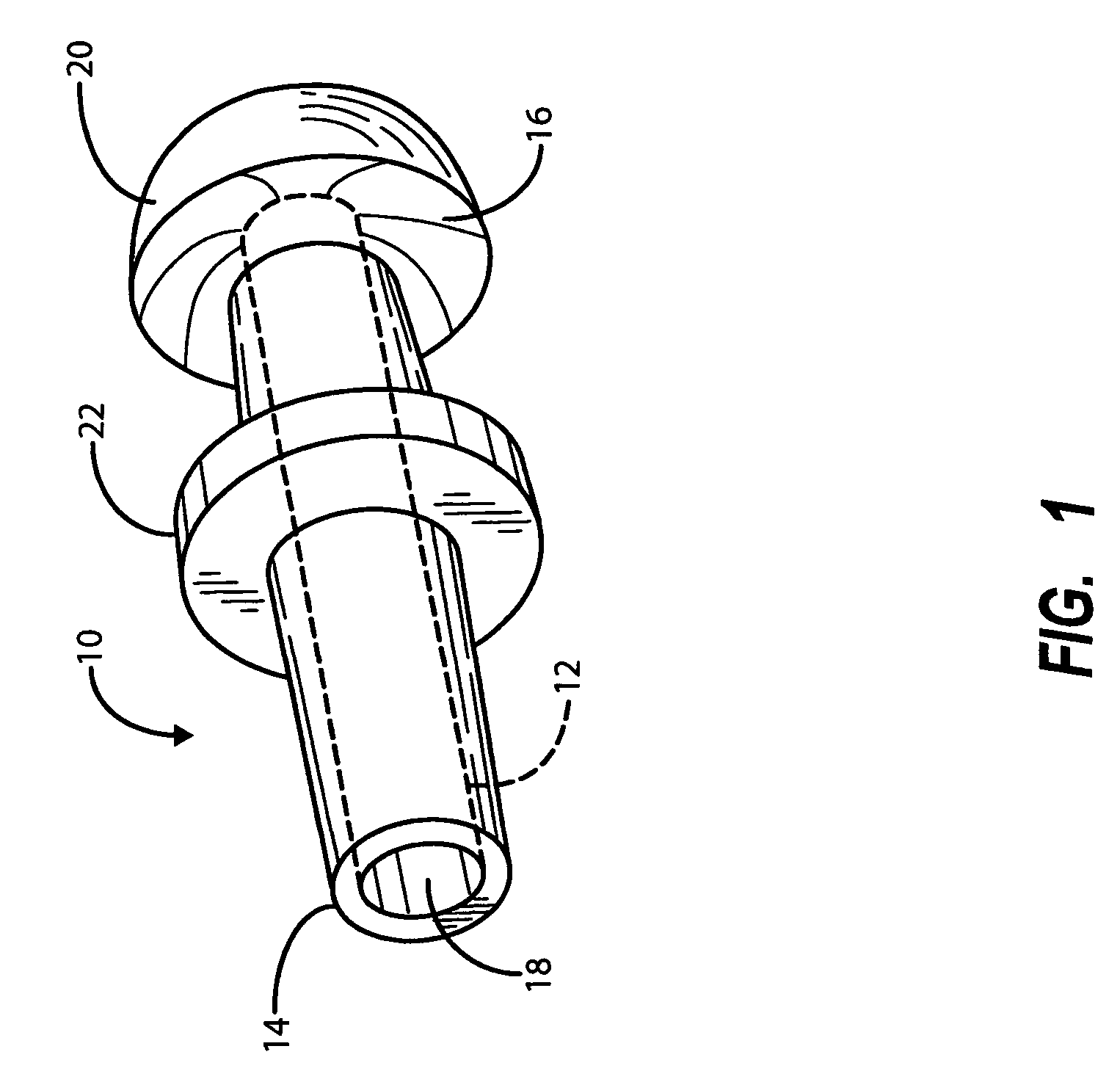
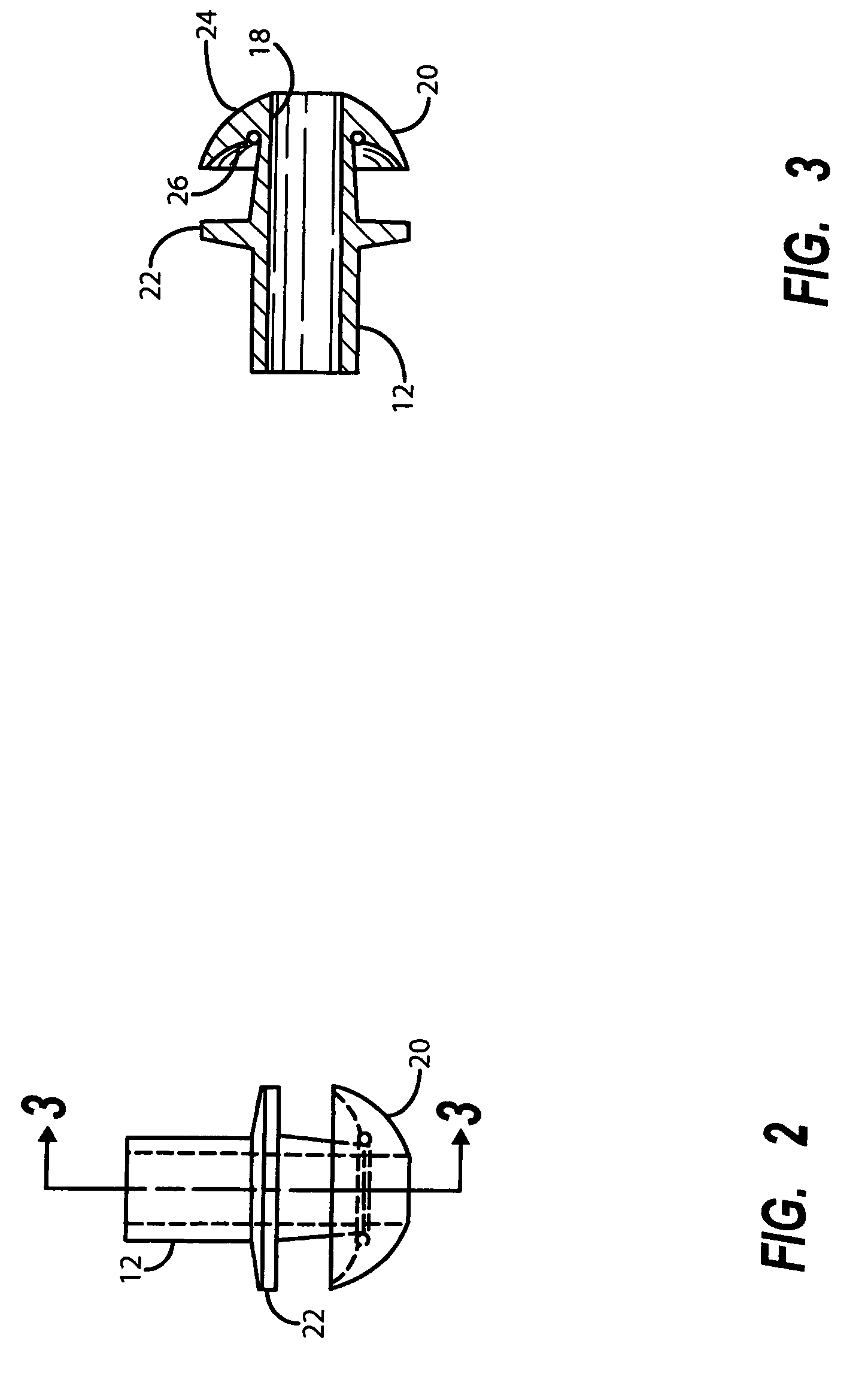
[0022]Referring first to FIG. 1, there is shown a isometric view of a stent especially designed for placement in the ostium of the sphenoid sinus in the treatment of sphenoid sinusitis. It is indicated generally by numeral 10 and comprises a soft compressible plastic tube 12 of a predetermined outer diameter and having a proximal end 14, a distal end 16 and a lumen 18 extending therebetween. A distal end portion of the tube 12 is tapered and terminates in a integrally formed, generally hemispherical hollow dome 20 whose diameter is greater than the predetermined diameter of the plastic tube 12. The lumen 18 extends all the way through the surface of the dome 20.

[0023]A short predetermined distance proximal of the distal end 16 of the tube 12 is an integrally formed, radially extending flange 22, the diameter of which is generally equal to the diameter of the hemispherical dome 20. The stent is preferably formed in a molding operation from a suitable plastic. Without limitation, the ...


PUM


Abstract

A stent specifically designed for use in treating chronic sphenoid sinusitis comprises a soft compressible plastic tube of a predetermined diameter having a proximal end, a distal end and a lumen extending therebetween. The stent has a generally hemispherical hollow dome integrally molded to its distal end. The diameter of the dome is greater than the predetermined diameter of the plastic tube. The stent further includes an integrally molded annular flange located a short predetermined distance proximal to the hemispherical dome. The device is designed to be fitted through a surgically enlarged ostium of the sphenoid sinus such that the dome resides within the sinus cavity and the flange abuts the bony wall surrounding the ostium. The stent maintains the ostium patent and permits irrigation/suctioning via the stent's lumen.

Description

BACKGROUND OF THE INVENTION[0001]I. Field of the Invention[0002]This invention relates generally to stents for maintaining a passageway in an animal body patent, and more particularly to a stent specifically designed for use in treating chronic sinusitis where the sphenoid sinus is involved.[0003]II. Discussion of the Prior Art[0004]The paranasal sinuses are air-filled pockets located within the bones of the face and around the nasal cavity. Each sinus is named for the bone in which it is located, e.g., maxillary, ethmoid, frontal and sphenoid.[0005]Each of these air-filled pockets has an opening that connects to the nose. This opening is called an ostium.[0006]The nose and sinuses are closely related. The nasal septum divides the nose into two nasal cavities. The sidewall of the nose (the lateral nasal wall) has three important structures, which are known as the superior, middle and inferior turbinates sometimes referred to as nasal concha. Each is a rounded projection that extends...

Claims


Application Information

Patent Timeline
IPC IPC(8): A61F2/06A61F2/82
CPCA61F2/02A61F2/82A61F2/186
Inventor DUNCAVAGE, JAMESHOOGENAKKER, JON E.ROBB, BRADLEY D.
Owner MICROMEDICS
Why Eureka
Try Eureka