Plasma display panel with porous pad

a technology of display panel and porous pad, which is applied in the direction of electrical apparatus construction details, identification means, instruments, etc., can solve the problems of large rear noise/vibration of pdp, and achieve the effect of minimizing noise/vibration

Inactive Publication Date: 2007-06-26
LG ELECTRONICS INC
View PDF11 Cites 19 Cited by
  • Summary
  • Abstract
  • Description
  • Claims
  • Application Information

AI Technical Summary

Benefits of technology

[0014]Accordingly, it is an object of the present invention to provide a plasma display panel that is adaptive for minimizing noise / vibration generated therefrom.

Problems solved by technology

Recently, various flat panel devices have been developed that reduce weight and bulk, which are drawbacks of the cathode ray tube (CRT).
As a result, rear noise / vibration of the PDP is greatly increased in comparison with noise / vibration generated from the printed circuit board 16 itself.

Method used


Image

  • Plasma display panel with porous pad
  • Plasma display panel with porous pad
  • Plasma display panel with porous pad

Examples


first embodiment

[0046]Referring to FIG. 3A and FIG. 3B, a plasma display panel (PDP) according to the present invention includes a display panel 22 for displaying a picture, a frame (or heat-proof panel) 28, a porous pad 32 for preventing noise / vibration generated from the display panel 22 from being transferred to the frame 28; and a printed circuit board 36.

[0047]The display panel 22 includes a front substrate 26 and a rear substrate 24. The rear substrate 24 is coated with a phosphorous material (not shown). The front substrate 26 transmits light generated from the phosphorous material to thereby display a desired picture.

[0048]The rear substrate 24 of the display panel 22 is adhered with a porous pad 32, by which the display panel 22 is joined with the frame 28. Since the porous pad 32 has a function of absorbing noise and vibration, it absorbs and shields against propagation of noise / vibration, generated upon driving of the display panel 22, to the frame. Also, since the porous pad 32 has a he...

second embodiment

[0054]Referring to FIG. 6, a plasma display panel (PDP) according to the present invention includes a display panel 52 for displaying a picture, a frame (or heat-proof panel) 58, a heat-conductive double-faced tape 64 provided between the display panel 52 and the frame 58, a porous pad 62 provided between the heat-conductive double-faced tape 64 and the frame 58 to prevent noise / vibration generated from the display panel 52 from being transferred to the frame 58, and a printed circuit board 66.

[0055]The display panel 52 includes a front substrate and a rear substrate (not shown). The rear substrate is coated with a phosphorous material (not shown). The front substrate transmits light generated from the phosphorous material to thereby display a desired picture.

[0056]The rear substrate of the display panel 52 is adhered with the heat-conductive double-faced tape 64, by which the display panel 52 is joined with the frame 58. The heat-conductive double-faced tape 64, made of a material ...

third embodiment

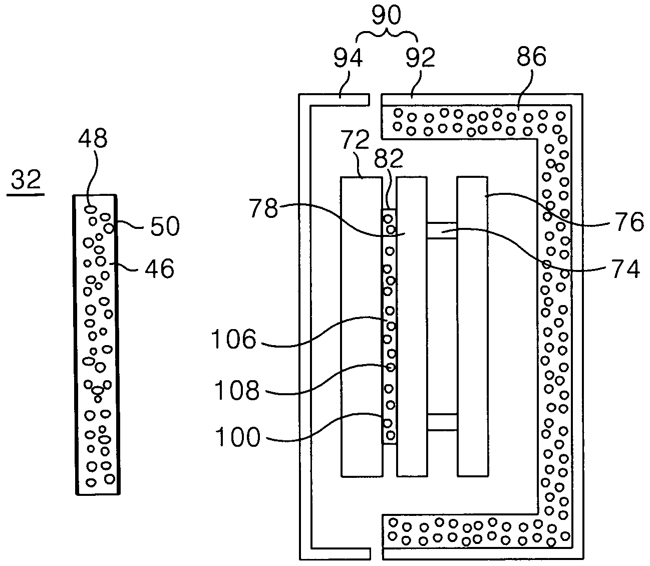
[0063]Referring to FIG. 7, a plasma display panel (PDP) according to the present invention includes a display panel 72 for displaying a picture, a frame (or heat-proof panel) 78, a first porous pad 82 for preventing noise / vibration generated from the display panel 72 from being transferred to the frame 78, and a printed circuit board 76.

[0064]The display panel 72 includes a front substrate and a rear substrate (not shown). The rear substrate is coated with a phosphorous material (not shown). The front substrate transmits light generated from the phosphorous material to thereby display a desired picture.

[0065]The rear substrate of the display panel 72 is adhered with the first porous pad 82, by which the display panel 72 is joined with the frame 78. Since the first porous pad 82 has a function of absorbing noise and vibration, it absorbs and shields against propagation of noise / vibration, generated upon driving of the display panel 72, to the frame 78. Also, since the first porous pa...


PUM


Abstract

A plasma display panel adapted to minimize noise/vibration as well as a heat generated therefrom. In the plasma display panel, a display panel displays a picture while a porous pad is provided behind the display panel to prevent the transfer of noise/vibration to an associated heat proof panel. When the PDP is mounted within a case, a second porous pad can be provided on an inner surface of the case opposite the display panel and adjacent to an associated printed circuit board for additional noise/vibration damping.

Description

BACKGROUND OF THE INVENTION[0001]1. Field of the Invention[0002]This invention relates to a plasma display panel and, more particularly, to a plasma display panel that is adaptive for minimizing noise / vibration and heat generated therefrom.[0003]2. Description of the Related Art[0004]Recently, various flat panel devices have been developed that reduce weight and bulk, which are drawbacks of the cathode ray tube (CRT). Such flat panel display devices include a liquid crystal display (LCD), a field emission display (FED), a plasma display panel (PDP) and an electro-luminescence display (ELD), etc.[0005]The PDP of these flat panel display devices allows an ultraviolet ray, generated upon discharge of an inactive mixed gas, such as He+Xe, Ne+Xe or He+Xe+Ne, etc., to radiate a phosphorous material to thereby display a picture. The PDP has been used for high-resolution television, monitors and as an internal or external advertising display because it has a rapid response speed and is suit...

Claims


Application Information

Patent Timeline
Patent Type & Authority Patents(United States)
IPC IPC(8): H01J17/49G09F9/00H01J17/16H01J17/28H05K7/20
CPCH05K7/20963H01J2217/492H01J11/10H01J17/16H01J17/28
Inventor JUN, JAE HONGKIM, JIN YOUNGSONG, YONGKIM, DEOK SOOKIM, WON TAELEE, CHUL HWANJUNG, HAE YOUNG
Owner LG ELECTRONICS INC
Why Eureka
Try Eureka