Ground control unit for cable locating

Inactive Publication Date: 2007-06-26
AMERICAN TELEPHONE & TELEGRAPH CO
View PDF3 Cites 4 Cited by
  • Summary
  • Abstract
  • Description
  • Claims
  • Application Information

AI Technical Summary

Benefits of technology

[0008]The inventive system provides the ability to remotely control all lateral ground points thereby eliminating the need for a technician to travel to each customer location and manually apply or remove the ground. This methodology reduces plant protection time and increases the efficiency of maintenance personnel at a dig location.

Problems solved by technology

Conversely, the side leg cable having a larger impedance (i.e., a longer signal path to the cable locating signal generator) will radiate a lower strength locating signal, making locating of such a side-leg cable more difficult.
Such locating signal generators are expensive, and adding a separate locating signal generator for each side-leg will greatly increase costs.

Method used


Image

  • Ground control unit for cable locating
  • Ground control unit for cable locating

Examples


Embodiment Construction

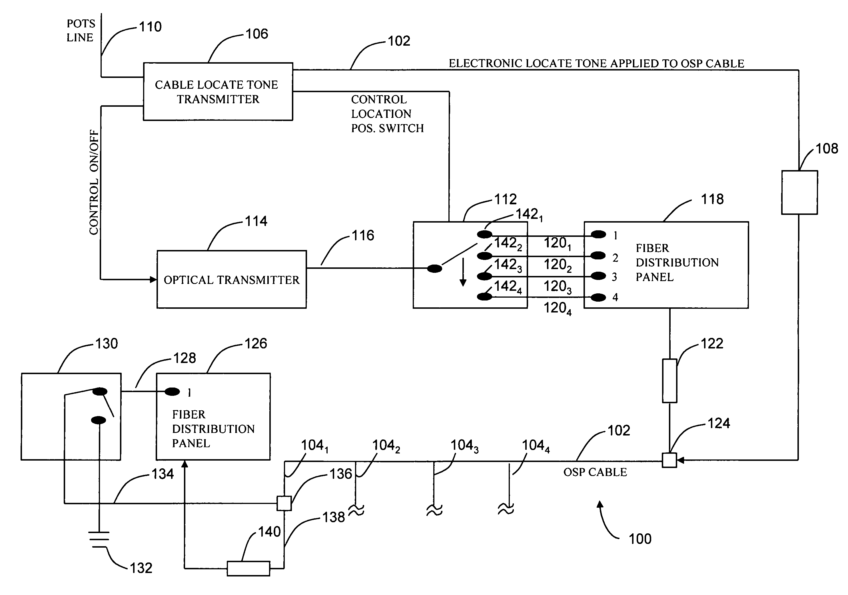
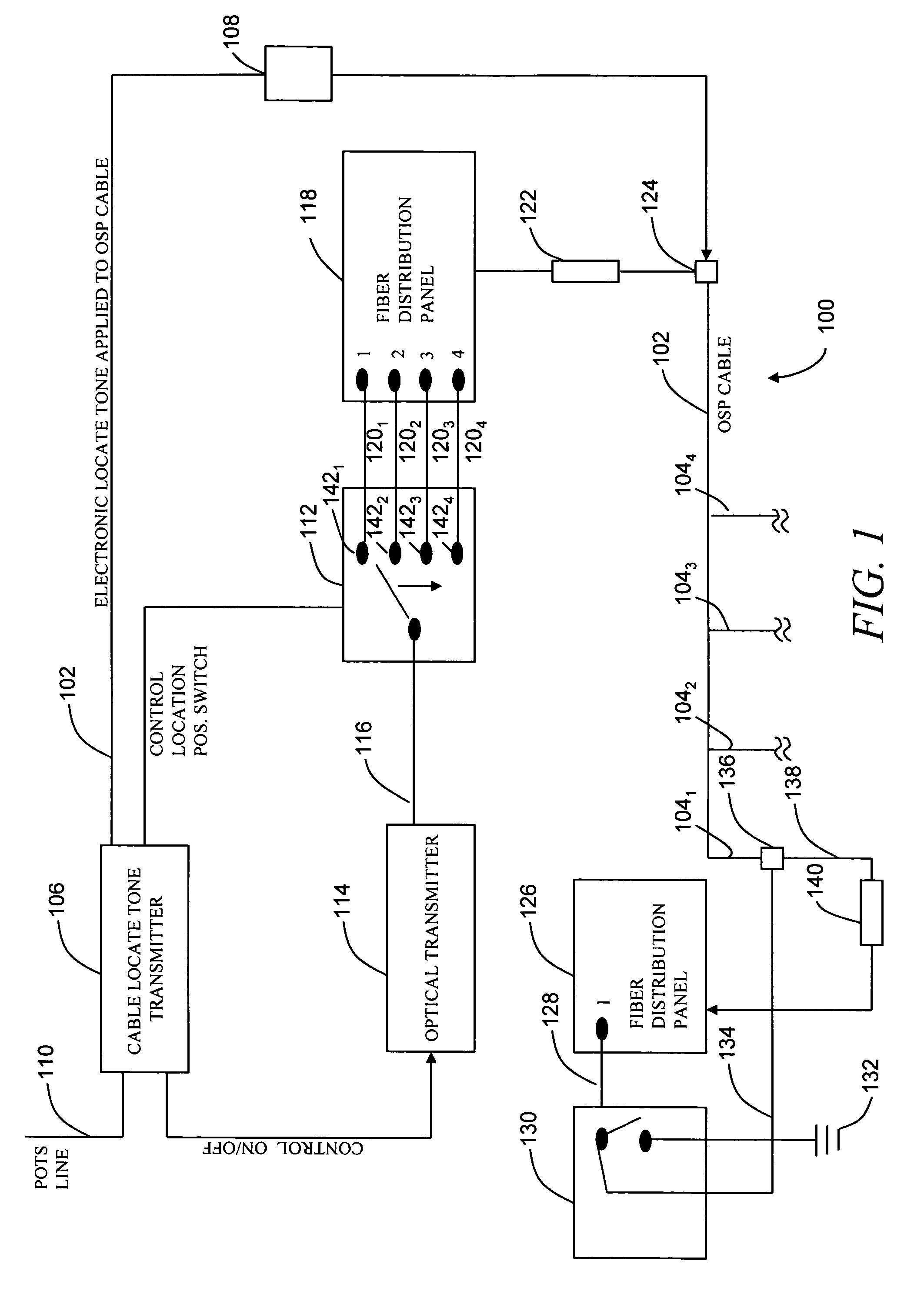
[0011]FIG. 1 depicts a schematic diagram of an exemplary telecommunications system 100 that includes a long-haul (backbone) outside the plant (OSP) fiber optic cable 102 coupled to a plurality of short-haul side-leg cables 1041, 1042, 1043, and 1044 (collectively “side-legs 104”). The side-legs 104 each serve a respective customer location 1–4. The backbone cable 102 typically comprises a buried fiber optic cable that includes one or more individual optical fibers and a metallic sheath (not shown). The side-leg cables 104 each run from the backbone cable 102 to a separate telecommunications facility at the customer locations (not shown). The long-haul and short-haul cables are also referred to as utility conveyances as will be appreciated by those skilled in the art. Although four side-leg cables 104 are depicted in the illustrative drawing, the cable route could include a larger or smaller number of side-leg cables and corresponding customer locations.

[0012]To enable the location o...


PUM


Abstract

A system for selectively grounding each of a plurality of short-haul buried utility conveyances coupled to a common long-haul buried utility conveyance to enable a conveyance locating signal transmitted through the long-haul conveyance to travel from the long-haul utility conveyance to a selected short-haul utility conveyance. The system includes a first optical switch for selecting each of the plurality of short-haul utility conveyances to be grounded, where the first optical switch is adapted to receive an optical signal and selectively output the optical signal on one of a plurality of optical fibers; and a second optical switch coupled to each of the plurality of optical fibers for grounding each short-haul utility conveyance in response to the optical signal on a corresponding optical fiber.

Description

BACKGROUND OF THE INVENTION[0001]The present invention relates generally to locating an underground utility conveyance, and more particularly, to a method and apparatus for selectively locating a short-haul cable or pipe that is coupled to a long-haul (backbone) cable.[0002]Many utilities, such as AT&T Corp., bury their pipes and cables (“utility conveyances”) underground both for reasons of safety and esthetics. Underground burial often provides protection to such utility conveyances against weather and other sources of potential damage. Utilities that undertake burial of their conveyances usually make extensive efforts to plot the location of each buried conveyance on a map to facilitate its location in case of repair or replacement. While a map will indicate the general location of a buried conveyance, more precise location information often becomes necessary, particularly in urban environments. For that reason, most utilities that bury their conveyances underground typically rel...

Claims


Application Information

Patent Timeline
IPC IPC(8): G01R19/00
CPCG01R29/085
Inventor ESLAMBOLCHI, HOSSEINHUFFMAN, JOHNBOLAND, JOHN K.TURLEY, CLAYWELL D.
Owner AMERICAN TELEPHONE & TELEGRAPH CO
Why Eureka
Try Eureka