Adjustable resonator filter

a resonator filter and adjustment technology, applied in the field of resonator filters, can solve the problems of affecting the natural frequency of a certain resonator of different filters, requiring a bit of mechanism, and consuming a lot of time to adjust, so as to achieve simple electric control, increase reliability, and reduce the effect of additional losses

Inactive Publication Date: 2007-06-26
INTEL CORP
View PDF13 Cites 24 Cited by
  • Summary
  • Abstract
  • Description
  • Claims
  • Application Information

AI Technical Summary

Benefits of technology

[0011]An advantage of the invention is that when the subband division is in use, the filters need not be separately adjusted for each subband in connection with the manufacture, because the selection of the subband can take place when the filter is put into use by a simple adjustment. In addition, the invention has the advantage that the additional losses caused by the adjusting arrangement of the filter are very low. Furthermore, the invention has the advantage that at least inside the resonator cavities no moving parts are required, which means increased reliability. A further advantage of the invention is that when electronic switches are used, the adjusting of the filter can be implemented by simple electric control.
is that when the subband division is in use, the filters need not be separately adjusted for each subband in connection with the manufacture, because the selection of the subband can take place when the filter is put into use by a simple adjustment. In addition, the invention has the advantage that the additional losses caused by the adjusting arrangement of the filter are very low. Furthermore, the invention has the advantage that at least inside the resonator cavities no moving parts are required, which means increased reliability. A further advantage of the invention is that when electronic switches are used, the adjusting of the filter can be implemented by simple electric control.

Problems solved by technology

In serial production, the variation of the natural frequency of a certain resonator of different filters is generally too wide with regard to the filter requirements.
However, such adjustment is time-consuming and relatively expensive, because tuning has to be implemented manually in several iteration steps in order to achieve the desired frequency response. FIG. 1a,b presents a resonator filter known by the applicant from the application FI20030402, the passband of which can be shifted by a one-time adjustment.
The structure is relatively compact, but moving the tuning piece requires a bit of mechanism.

Method used


Image

  • Adjustable resonator filter
  • Adjustable resonator filter
  • Adjustable resonator filter

Examples


Embodiment Construction

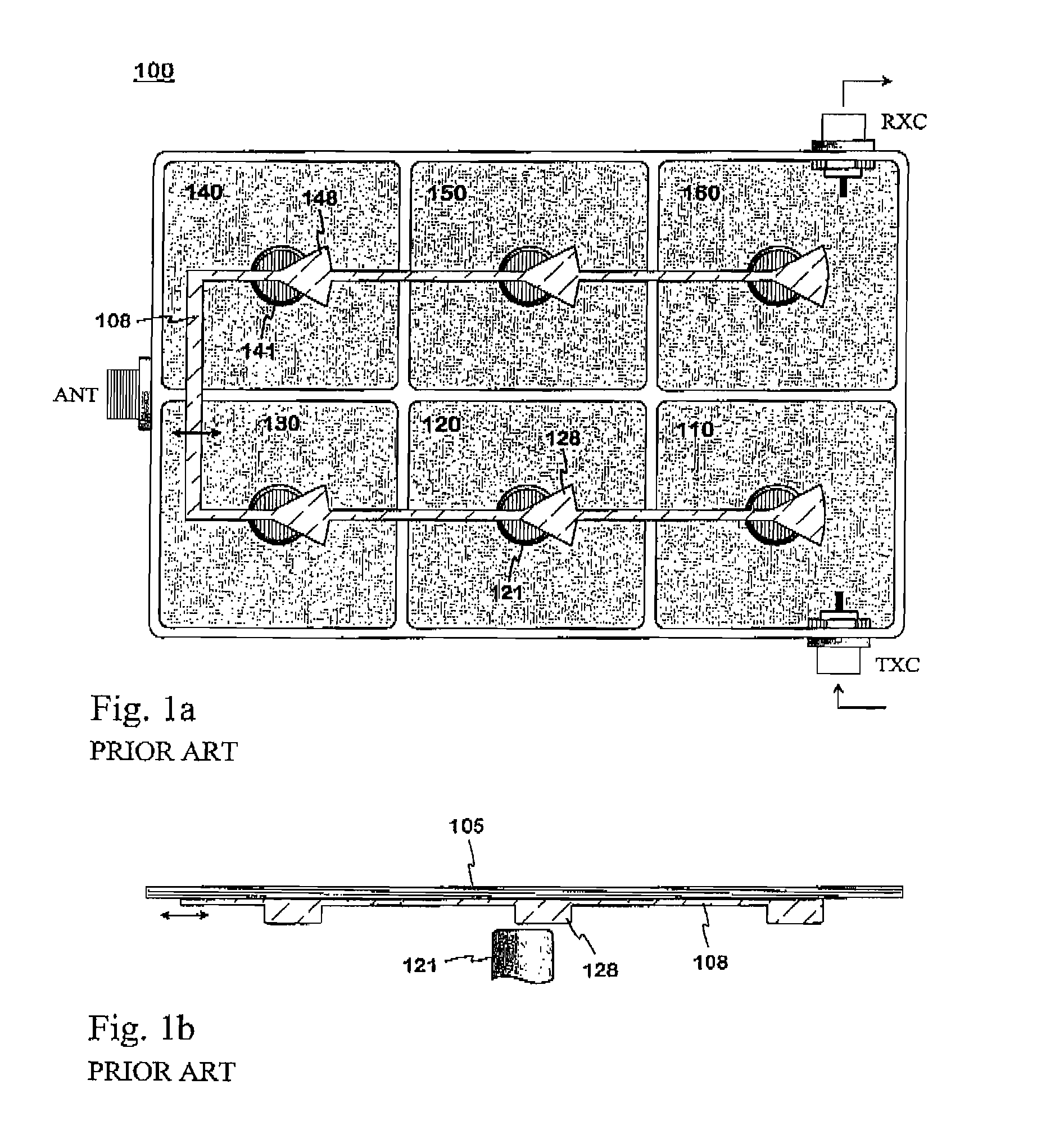
[0024]FIGS. 1a and 1b were already explained in connection with the description of the prior art.

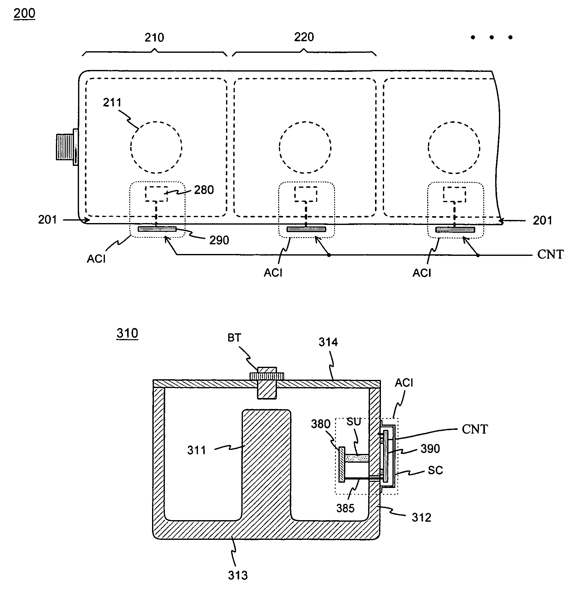
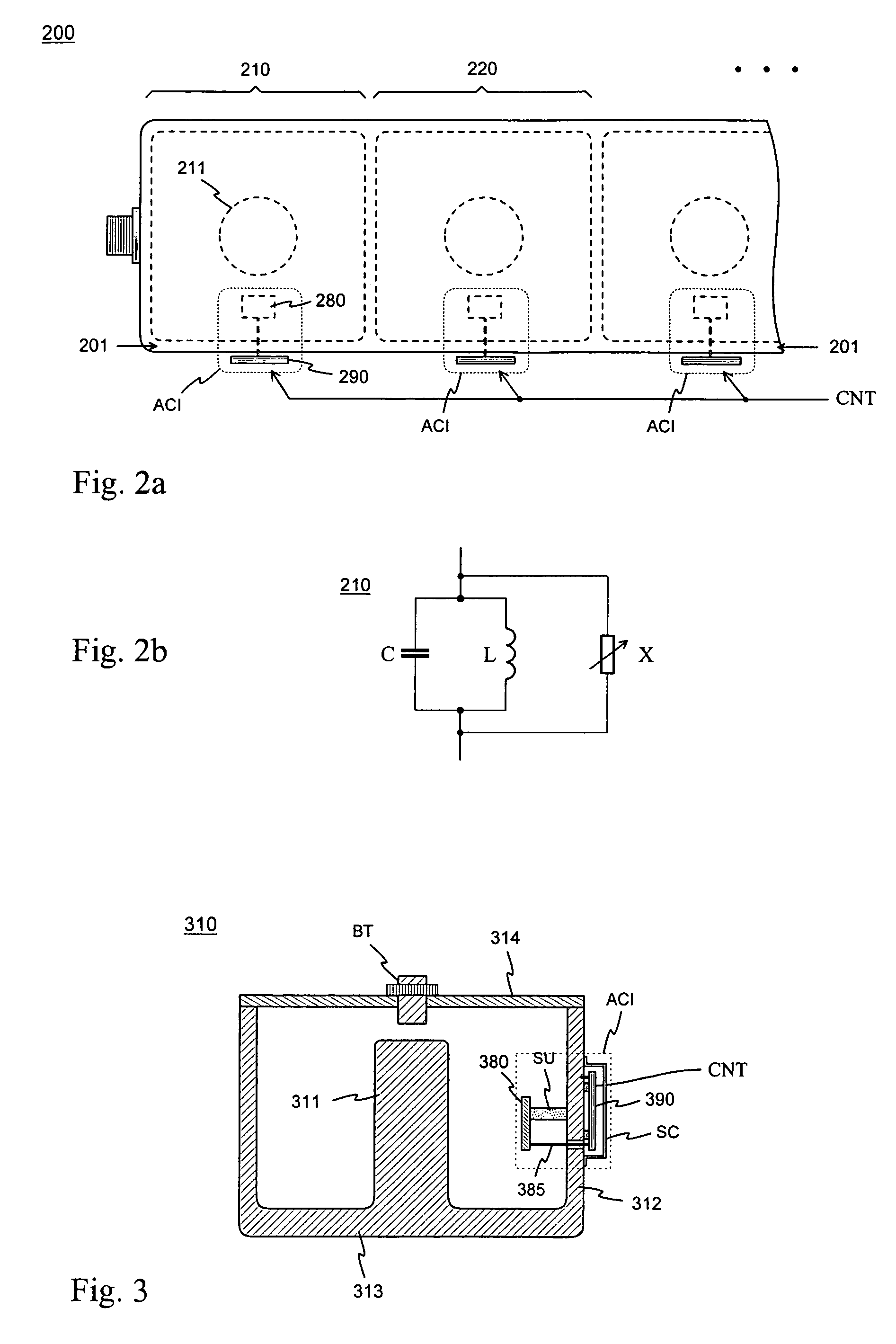
[0025]FIG. 2a is a structural drawing presenting the principle of a resonator filter according to the invention. The filter 200 is seen in the figure from above when the cover is in place. In it there are in a united and conductive filter housing resonators in succession, such as a first resonator 210 and a second resonator 220. In the cavity of the first resonator there is an element 211 belonging to the basic structure of the resonator, and there is a similar element in the other resonators. Each resonator is equipped with an adjustment circuit ACI, which includes a fixed tuning element 280 and an adjusting part 290. The tuning element is conductive and it is located in the resonator cavity, for which reason it has an electromagnetic coupling to the basic structure of the resonator. The adjusting part 290 is located outside the resonator cavity, in the exemplary drawing beside the side...


PUM


Abstract

An adjustable resonator filter (200), the operating band of which can be shifted by a one-time adjustment. The natural frequency of each resonator (210, 220) is affected, in addition to the basic tuning arrangement, by an adjustment circuit (ACI), which includes a fixed tuning element (280) in the resonator cavity and an adjusting part (290) outside the cavity. The tuning element has an electromagnetic coupling to the basic structure of the resonator. The adjustment circuit is functionally a short transmission line, which is “seen” by the resonator as a reactance of a certain value. By changing the electric length of the transmission line, the value of the reactance and the electric length and natural frequency of the whole resonator are changed. The change is implemented in the adjustment part by means of switches or a movable dielectric piece. In the resonator filter each resonator has a similar adjustment circuit, and the adjustment circuits have common control (CNT) for shifting the band of the filter. When the subband division is in use, the filters need not be separately adjusted for each subband in connection with the manufacture. No moving parts are required inside the filter housing.

Description

CROSS REFERENCE TO PRIOR APPLICATION[0001]This application is a continuation of International Patent Application Serial No. PCT / FI2005 / 50170, filed May 18, 2005, which claims priority of Finnish Application No. 20040786, filed Jun. 8, 2004, both of which are incorporated by reference herein.[0002]The invention relates to a filter consisting of resonators, the operating band of which can be shifted by a one-time adjustment. A typical application of the invention is an antenna filter of a base station.BACKGROUND OF THE INVENTION[0003]When a resonator filter is manufactured, its transmission characteristics, i.e. its frequency response, must be arranged to comply with the requirements. This requires that the strengths of the couplings between the resonators are correct and that the resonance frequency, or natural frequency, of each resonator has a pre-determined value especially in relation to the natural frequencies of other resonators. In serial production, the variation of the natur...

Claims


Application Information

Patent Timeline
Patent Type & Authority Patents(United States)
IPC IPC(8): H01P1/202H01P1/201H01PH01P1/20H01P1/205H01P1/207H01P1/208H01P7/04H01P7/10
CPCH01P1/2053H01P7/04H01P7/10
Inventor PUOSKARI, JUKKA
Owner INTEL CORP
Why Eureka
Try Eureka