Supercharge Your Innovation With Domain-Expert AI Agents!

Surveillance management system

a surveillance management and surveillance technology, applied in the field of surveillance systems, can solve the problems of not providing a means of easily determining when and where an event or condition has taken place, and video data to be recorded and archived for only a very limited period of time,

Inactive Publication Date: 2007-06-26
SIEMENS SWITZERLAND
View PDF2 Cites 16 Cited by
  • Summary
  • Abstract
  • Description
  • Claims
  • Application Information

AI Technical Summary

Benefits of technology

Enables detailed analysis and reporting of monitored events, predicts future occurrences, and optimizes storage by providing a comprehensive data management system for continuous surveillance, enhancing security monitoring without the need for extensive recording media.

Problems solved by technology

While these systems provide for capture and recordation of video data depicting the conditions and / or occurrences within the monitored area, they do not provide a means of easily determining when and where an occurrence or condition has taken place.
Nor do they provide for any means of analyzing the information depicted by the video data.
Further, as video data requires substantial recording media space for storage, it is common for video data to be recorded and archived for only a very limited period of time.
Further, known systems do not provide for any type of analysis of video data that would allow for a determination of, for example, how long an intruder has been in a monitored area; whether the intruder is alone; how the intruder got into the monitored area; where the intruder has previously been; what the intentions of the intruder might be or, where the intruder may be going to next.

Method used


Image

  • Surveillance management system
  • Surveillance management system
  • Surveillance management system

Examples


Embodiment Construction

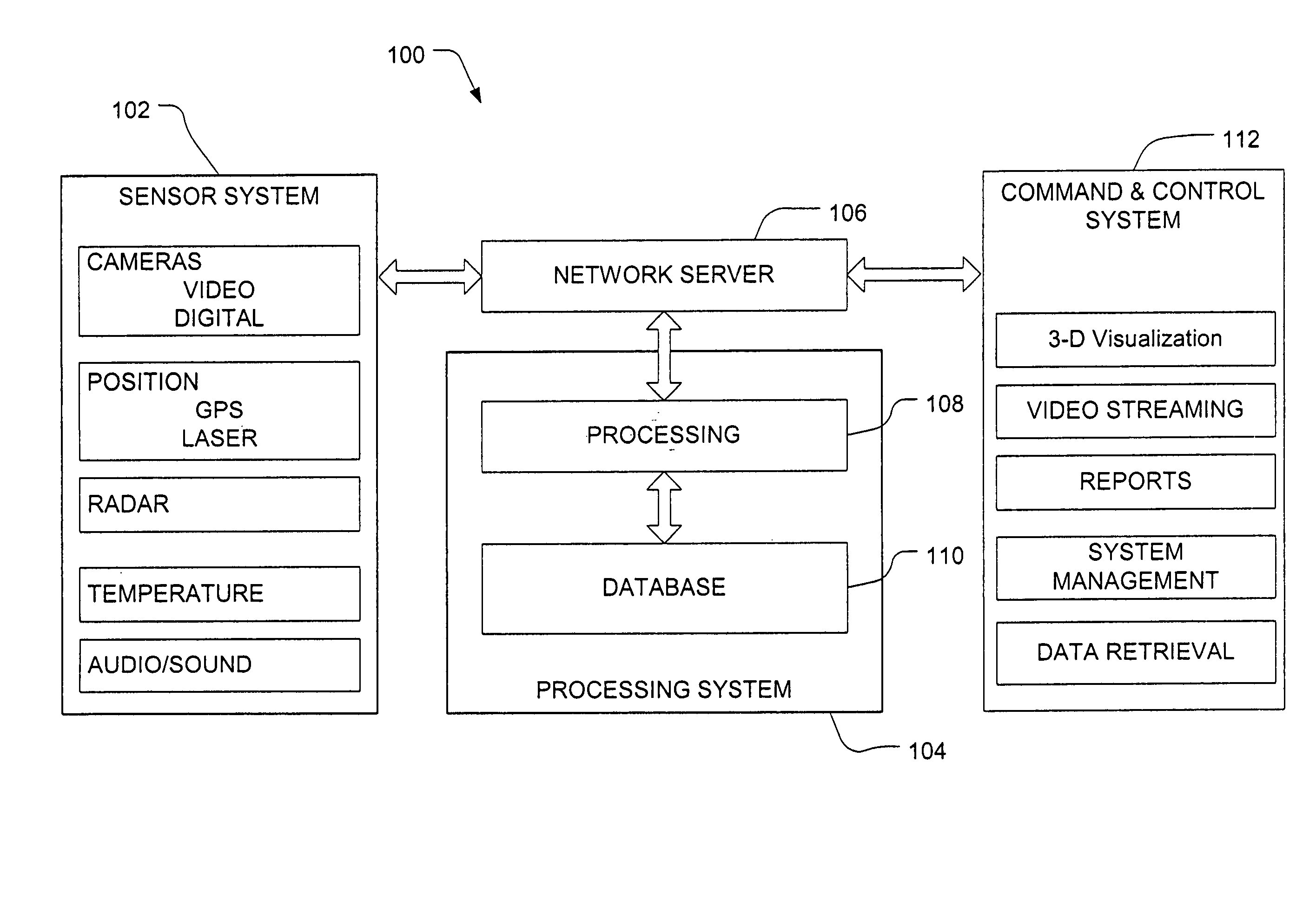
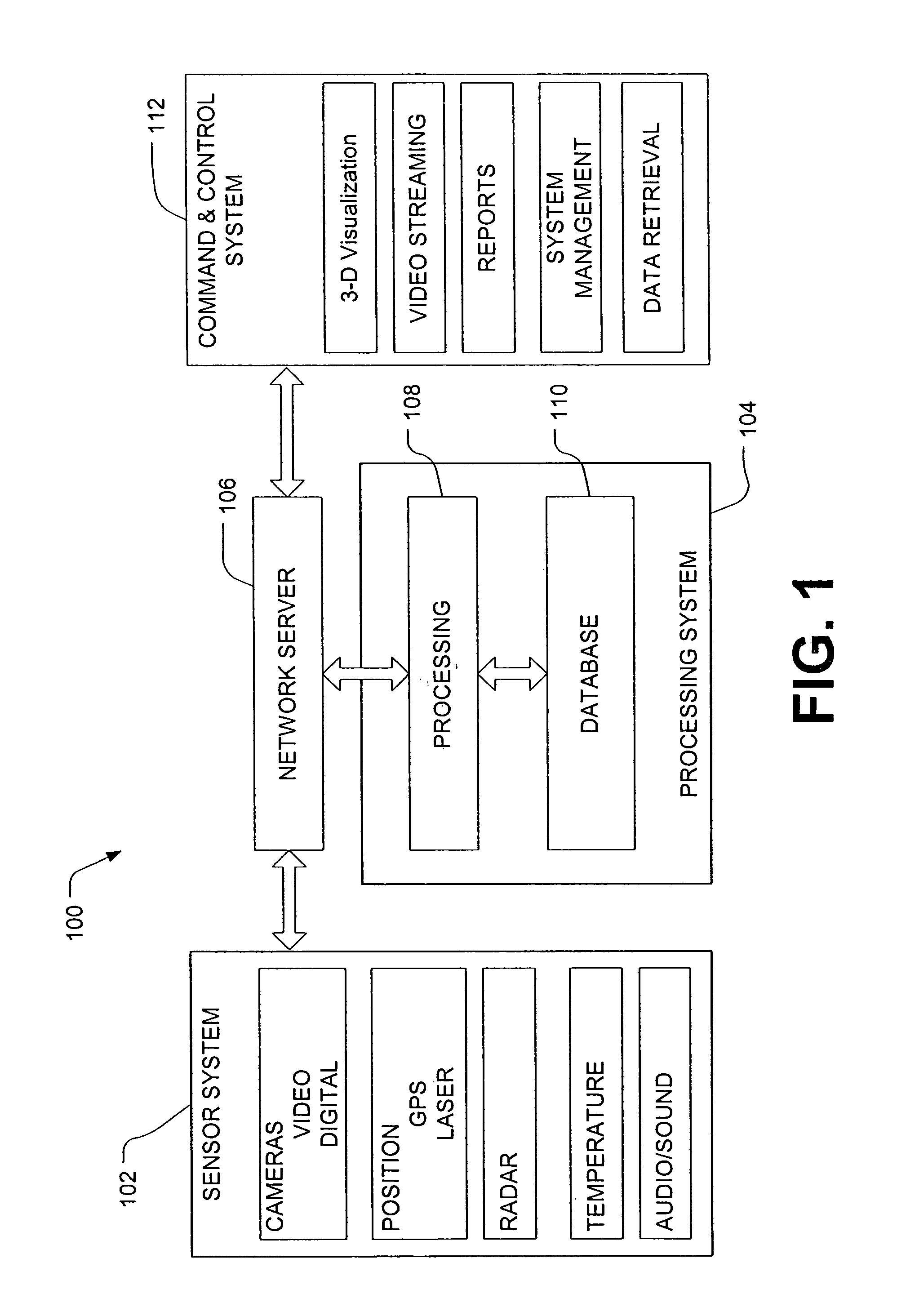
[0012]FIG. 1 is a block diagram representative of an embodiment of a surveillance system 100. The surveillance system 100 is structured to include a sensor system 102, a processing system 104, a network server 106 and a command and control system 112.

[0013]Sensor system 102 may include any type of detection or sensing device. Sensor system 102 may include one or more detection or sensing devices. Some examples of detection / sensing devices are: cameras, such as video or digital cameras; position sensors, such as global satellite positioning system (GPS) compliant receivers or transceivers, laser measurement devices and triangulation based positioning systems; radar, temperature detectors and the like. Further examples of detection / sensing devices include audio devices responsive to sound. These devices may be configured to capture audio data. The detection devices of sensor system 102 may be configured to capture and record captured data or to capture and transmit captured data to an...


PUM


Abstract

A system is provided for collecting surveillance data from one or more sensor units and incorporating the surveillance data into a surveillance database. The system is configured to retrieve surveillance data from the surveillance database and perform predetermined analytical functions on the data. The system is also configured to present surveillance data and the results of data analysis in one or more predetermined formats.

Description

CLAIM OF PRIORITY[0001]This application is a divisional of U.S. Patent Application No. 10 / 079,639, entitled “SURVEILLANCE SYSTEM,” filed Feb. 19, 2002, now U.S. Pat. No. 7,106,333, which claims the benefit of U.S. Provisional Application No. 60 / 269,434 entitled,“SCANNING CAMERA AND SURVEILLANCE SYSTEM,” filed Feb. 16, 2001, and U.S. Provisional Application No. 60 / 269,676 entitled, “SURVEILLANCE CAMERA SYSTEM,” filed on Feb. 16, 2001, and U.S. Provisional Application No. 60 / 317,635 entitled, “SURVEILLANCE SYSTEM,” filed on Sep. 6, 2001, the disclosures of which are entirely incorporated herein by reference.TECHNICAL FIELD[0002]The present invention is generally related to a surveillance system and more particularly, to a system for collection, analysis and distribution of surveillance data.BACKGROUND OF THE INVENTION[0003]Systems designed to monitor predetermined areas, places or objects are known. These systems often incorporate video cameras that provide a continuous feed of video ...

Claims


Application Information

Patent Timeline
Patent Type & Authority Patents(United States)
IPC IPC(8): G06T13/00
CPCG08B13/19613G08B13/19634G08B13/19645G08B13/19695G08B25/08
Inventor MILINUSIC, THOMISLAV F.
Owner SIEMENS SWITZERLAND
Features
  • R&D
  • Intellectual Property
  • Life Sciences
  • Materials
  • Tech Scout
  • Unparalleled Data Quality
  • Higher Quality Content
  • 60% Fewer Hallucinations
Learn More