
Method and apparatus for providing fair access to agents in a communication center

a communication center and agent technology, applied in the field of telephone communication, can solve the problems of difficult to ensure equal and fair access to agents for all callers, limited routing that can be done, and limited range of switches, although increasingly computerized

Inactive Publication Date: 2007-06-26
GENESYS TELECOMM LAB INC AS GRANTOR +3
View PDF6 Cites 268 Cited by
  • Summary
  • Abstract
  • Description
  • Claims
  • Application Information

AI Technical Summary

Benefits of technology

[0026]In embodiments of the invention described below in enabling detail, for the first time a system is provided for call centers wherein fair access can be provided to requests for service from multiple and disparate so

Problems solved by technology

If the call center consists of just a central switch and connected telephone stations, the routing that can be done is very limited.
Switches, although increasingly computerized, are limited in the range of computer processes that may be performed.
When incoming calls to a communication center are from different routing systems in a telephony network it becomes difficult to insure equal and fair access to agents for all of the callers.
This is due to various states of latency that exist in separate routing systems.
Because of this inconsistency over large portions of a telephony network, some callers or groups of callers to a communication center may inadvertently get much better service because of the fact that they are being routed over faster lines with better equipment.
In considering DNT networks, similar latency conditions exist that may cause some callers or groups of callers to receive poor service compared to those routed in over superior connections with superior equipment.

Method used


Image

  • Method and apparatus for providing fair access to agents in a communication center
  • Method and apparatus for providing fair access to agents in a communication center
  • Method and apparatus for providing fair access to agents in a communication center

Examples


Embodiment Construction

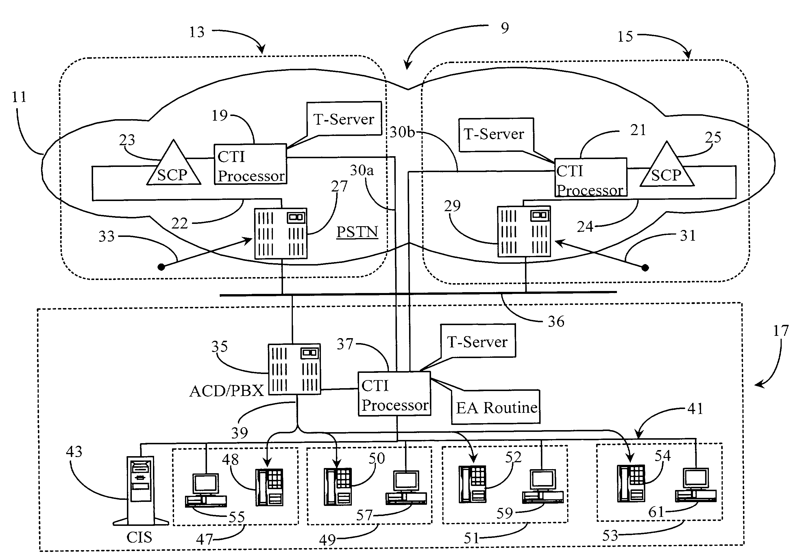
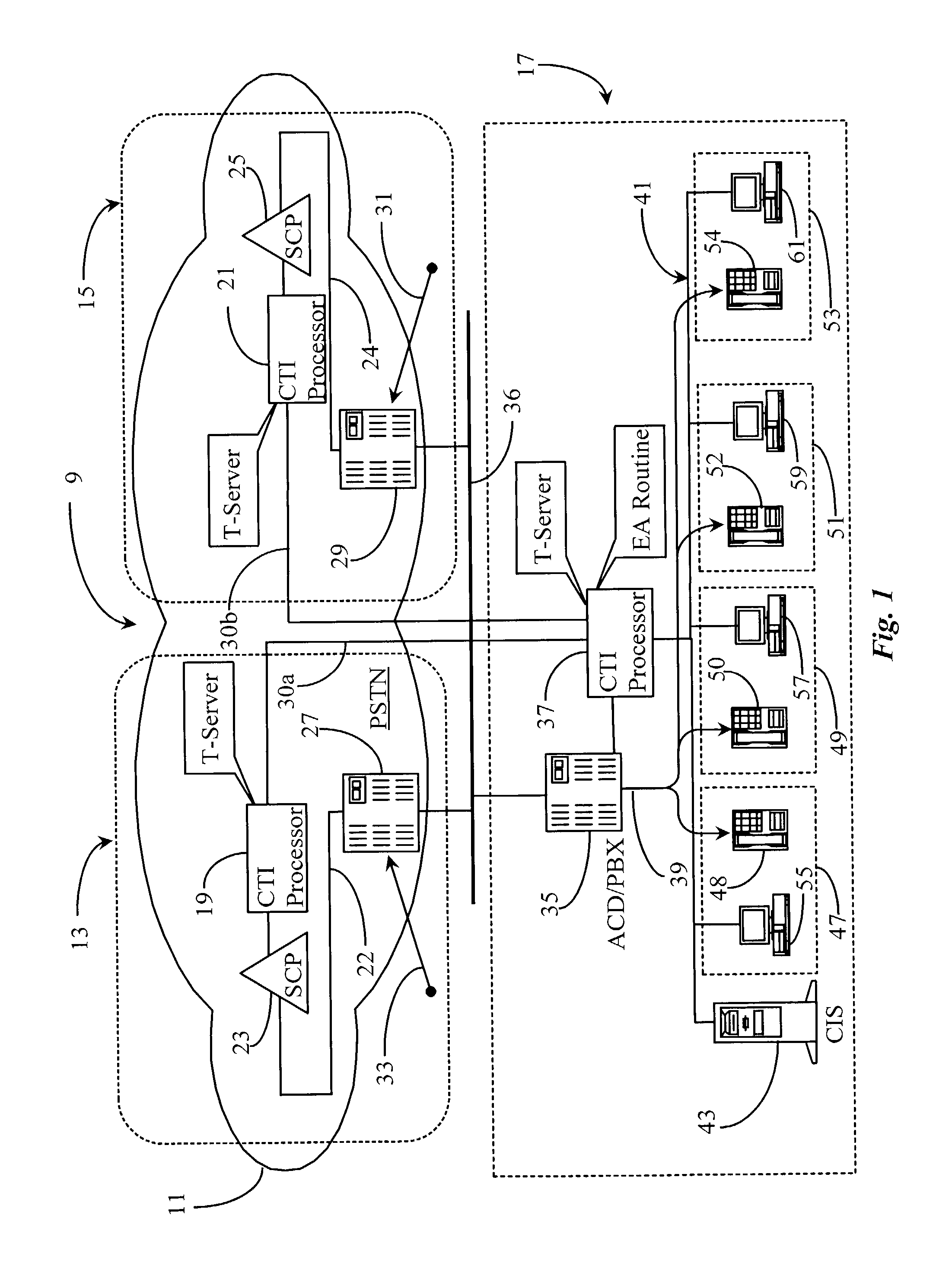
[0030]As described in the background section, latency variations inherent in different routing systems can cause inadvertent priority states to exist for callers and groups of callers attempting to secure available agents in a communication center. The inventor provides a CTI system that eliminates or at least significantly reduces undesired priority states that may exist due to such latency differences.

[0031]FIG. 1 is an overview of a network communication system 9 enhanced with the software and according to an embodiment of the present invention. Communication system 9 comprises a telephony network 11 and a connected communication center 17. Network 11 may be a PSTN network, an IPNT network, or a combination of the two. In this example, network 11 is a PSTN network and will serve to describe examples of the present invention.

[0032]Communication center 17 may be a large CTI service center, or any other type of CTI-enhanced communication center. Center 17 may also be capable of IPNT...


PUM


Abstract

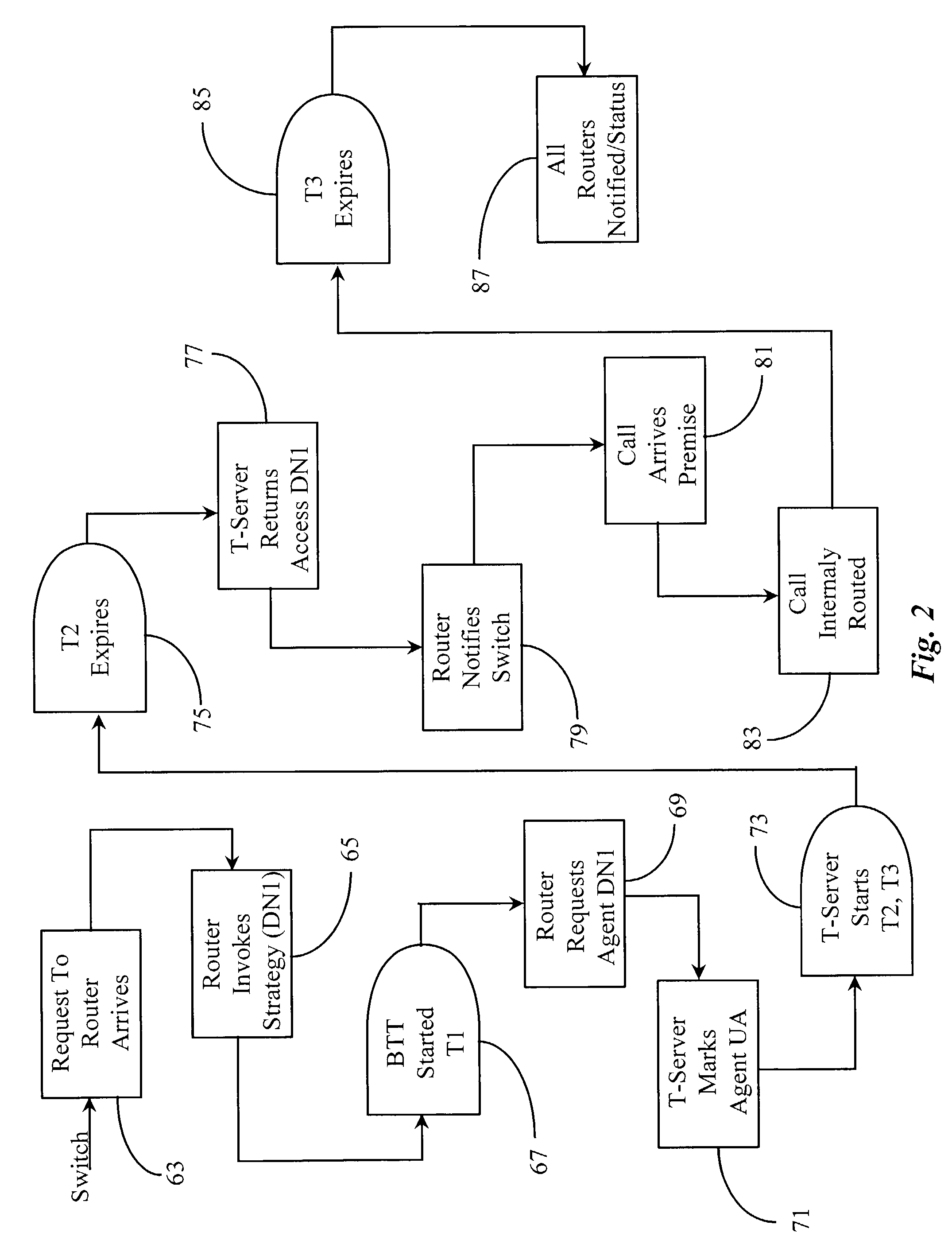
A system for granting access to agents at a communication center in response to requests for connection from network-level entities starts a fairness timer having a fairness time period when a first request is received for and agent, monitors any other requests for the same agent during the fairness time, and executes an algorithm at the end of the fairness time to select the network-level entity to which the request should be granted. In a preferred embodiment the fairness time is set to be equal to or greater than twice the difference between network round-trip latency for the longest latency and shortest latency routers requesting service from the communication center. In some embodiments an agent reservation timer is set at the same point as the fairness timer to prevent calls to the same agent, and has a period longer than the fairness timer by a time sufficient for a connection to be made to the agent station once access is granted, and for notification of the connection to be made to network-level entities.

Description

[0001]The present application is a continuation-in-part of U.S. patent application Ser. No. 09 / 335,423 filed Jun. 17, 1999, now U.S. Pat. No. 6,445,788FIELD OF THE INVENTION[0002]The present invention is in the field of telephony communication and has particular application to methods including software for routing incoming telephony calls from multiple service control points to agent-level in a communication center wherein equal access is afforded to callers from separate routing systems.BACKGROUND OF THE INVENTION[0003]Telephone call processing and switching systems arc, at the time of the present patent application, relatively sophisticated, computerized systems, and development and introduction of new systems continues. Much information on the nature of such hardware and software is available in a number of publications accessible to the present inventors and to those with skill in the art in general. For this reason, much minute detail of known systems is not reproduced here, a...

Claims


Application Information

Patent Timeline
IPC IPC(8): H04M5/00H04M3/51H04M3/523
CPCH04M3/5232H04M3/5237H04M3/5183H04M3/5234H04M2207/12
Inventor TORBA, DMITRIY A.
Owner GENESYS TELECOMM LAB INC AS GRANTOR
Learn More