Vehicle wheel state monitoring device and method

a technology of vehicle wheel and monitoring device, which is applied in the direction of vehicle tyre testing, mechanical roughness/irregularity measurement, instruments, etc., can solve the problems of inability to disclose any method for handling a situation, and inability to accurately detect abnormalities

Inactive Publication Date: 2007-06-26
TOYOTA JIDOSHA KK
View PDF13 Cites 8 Cited by
  • Summary
  • Abstract
  • Description
  • Claims
  • Application Information

AI Technical Summary

Benefits of technology

[0008]It is an object of the invention to provide a technology that can detect damage of a vehicle wheel caused by excessive input of load from a road surface in accordance with a type of vehicle wheel fitted to the vehicle.
[0012]According to this method, the threshold value is set in accordance with the type of the vehicle wheel. Thus, it is possible to appropriately determine whether damage has probably occurred in accordance with the type of the vehicle wheel.

Problems solved by technology

However, the above described technologies do not disclose any method for handling a situation when different types of run-flat tire wheels are fitted to the vehicle, such as run-flat tire wheels with reinforced sides or with an inner support ring.
Accordingly, in such situations, accurate abnormality detection may be impossible.

Method used


Image

  • Vehicle wheel state monitoring device and method
  • Vehicle wheel state monitoring device and method
  • Vehicle wheel state monitoring device and method

Examples


first embodiment

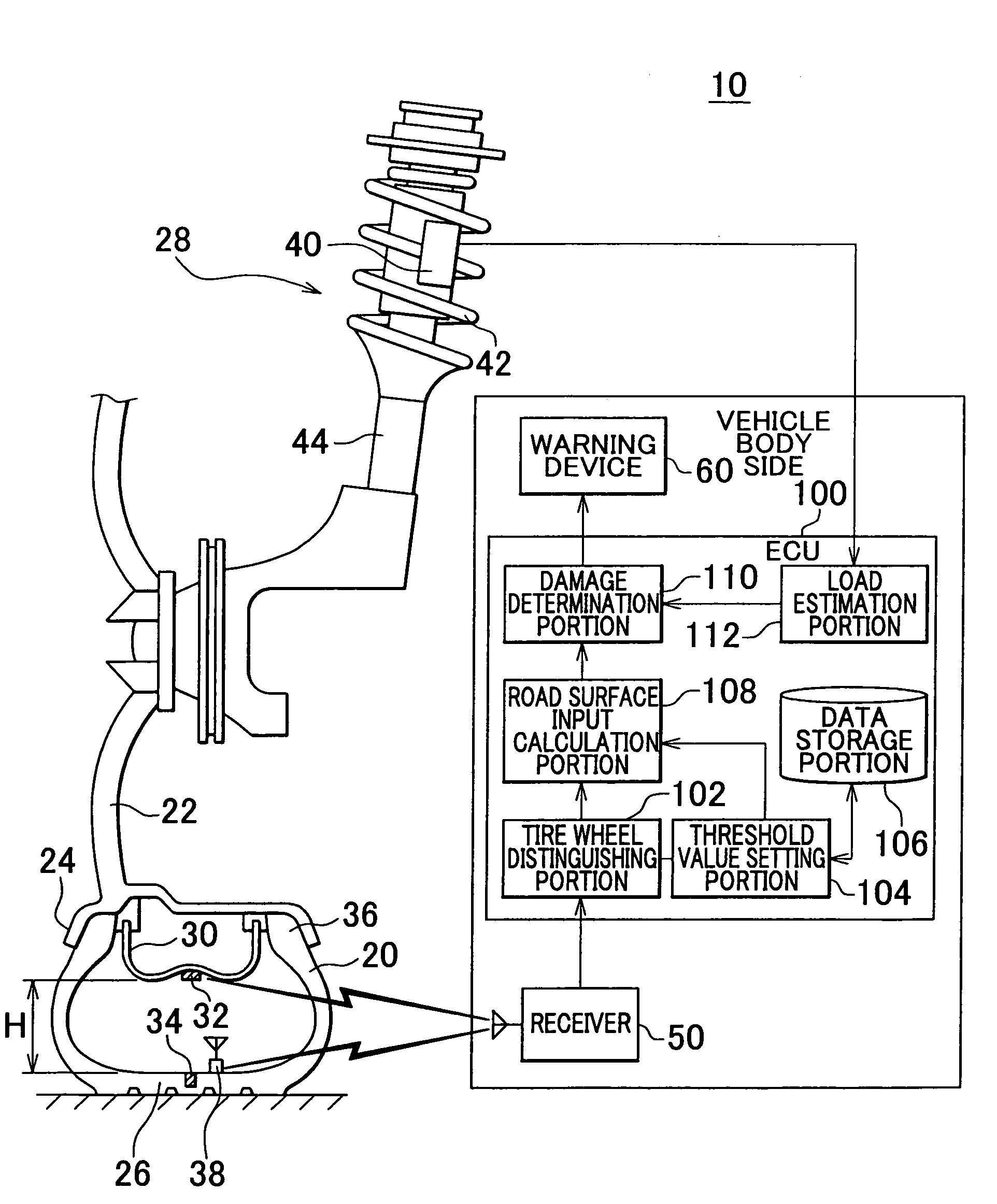
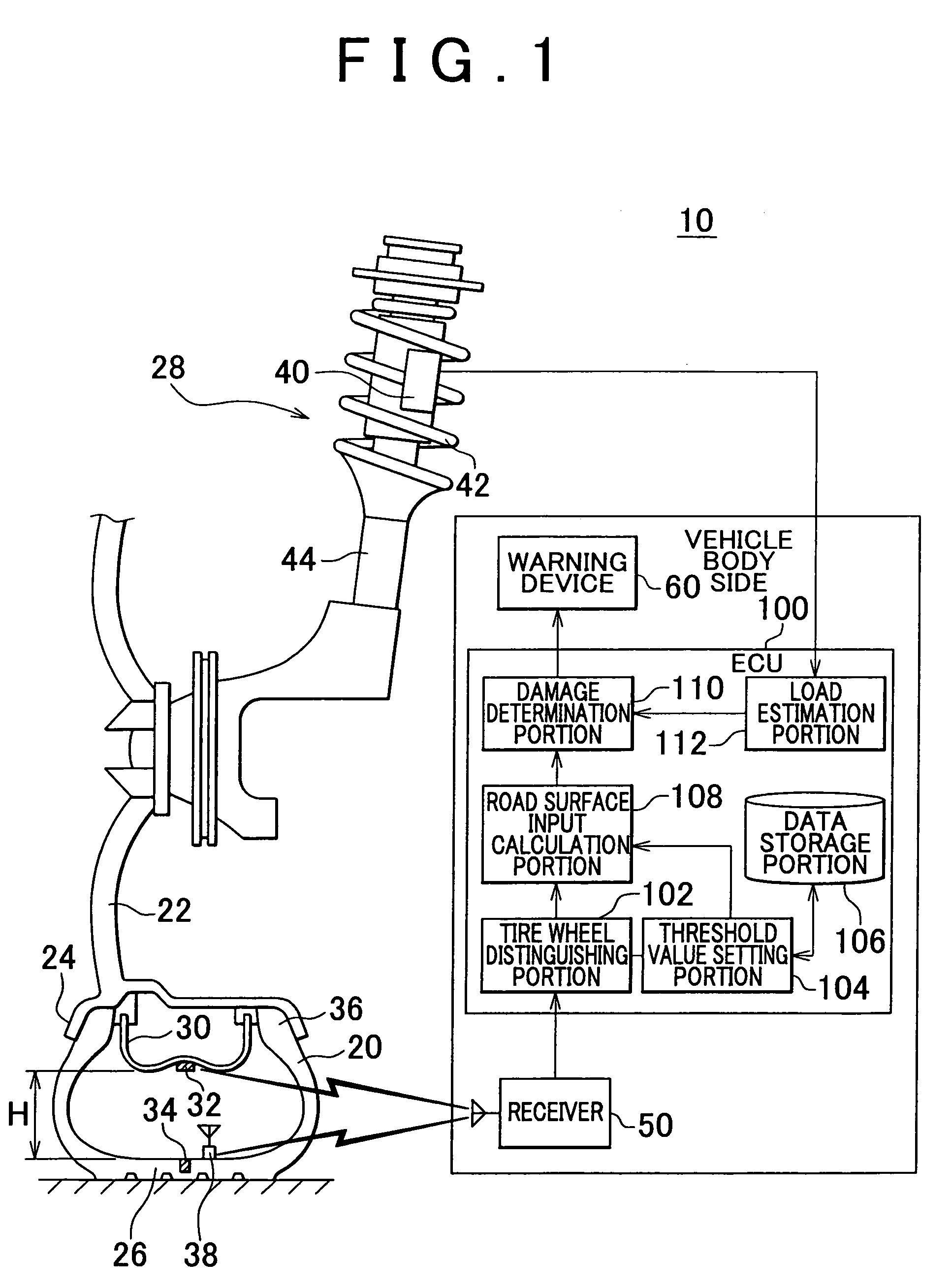
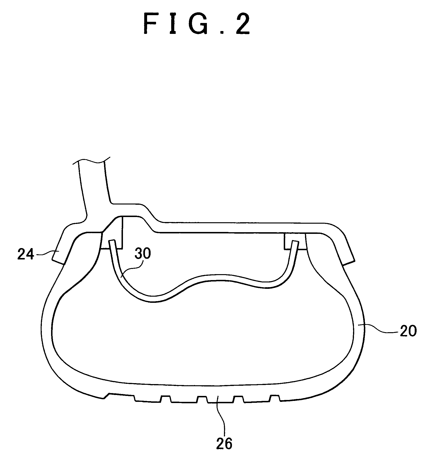
[0022]A structure of a vehicle wheel state monitoring device 10 according to the first embodiment will now be explained with reference to FIG. 1. FIG. 1 shows a part of a vehicle wheel such as a run-flat tire wheel with an inner support ring. Beads 36 of a tire 20 are fitted to a wheel rim 24 of a wheel 22. The tire 20 is fixed to the wheel 22 by filling air into the tire 20. A tread 26 of the tire 20 is the section that contacts with the ground and receives load of the vehicle. The wheel 22 is connected to a vehicle body, not shown, via a suspension 28. The suspension 28 mainly includes a coil spring 42 and a shock absorber 44. Note that structural members supported by a spring of the suspension 28 will be referred to as an “above spring portion”, and structural members not supported by the spring will be referred to as a “below spring portion”. More specifically, the above spring portion is on the side of the vehicle body, and the below spring portion is on the side of the vehicle...

second embodiment

[0055]In the first embodiment, the threshold value for determining whether damage has probably occurred is set in accordance with the type of vehicle wheel as described above. However, when the fitted vehicle wheel is an inner support ring run-flat tire wheel, there is a possibility that either (i) damage of the inner support ring or (ii) damage of the wheel may have occurred. Accordingly, separate determinations for damage of both of these portions may be performed. The structural configuration of a vehicle wheel state monitoring device according to a second embodiment is the same as that of the first embodiment shown in FIG. 1, and thus a drawing to illustrate the second embodiment is omitted here.

[0056]FIG. 6 is a flow chart according to the second embodiment showing a process for determining whether it is probable that a wheel is damaged. Steps S30 to S36 are the same as steps S10 to S16 of FIG. 5, and thus an explanation thereof is omitted here. The damage determination portion...


PUM


Abstract

A vehicle wheel state monitoring device appropriately determines whether it is probable that a vehicle wheel is damaged by setting a threshold value for damage determination in accordance with a type of the vehicle wheel fitted to the vehicle. A road surface input calculation portion calculates a road surface input that is a load applied to the tire based on an up-down direction force transmitted to the tire from a road surface. A damage determination portion determines whether it is probable that the vehicle wheel is damaged by comparing the road surface input and a threshold value that is pre-set. A vehicle wheel distinguishing portion receives information from a recording device provided on the vehicle wheel, and distinguishes the type of vehicle wheel fitted to the vehicle wheel. A threshold setting portion sets a threshold value in accordance with the distinguished type of the vehicle wheel.

Description

INCORPORATION BY REFERENCE[0001]The disclosure of Japanese Patent Application No. 2004-341281 filed on Nov. 25, 2005, including the specification, drawings and abstract is incorporated herein by reference in its entirety.BACKGROUND OF THE INVENTION[0002]1. Field of the Invention[0003]The invention relates to a vehicle wheel state monitoring device and method, and more particularly to a technology that monitors whether it is probable that a vehicle wheel is damaged during running of a vehicle.[0004]2. Description of the Related Art[0005]In order to run a vehicle safely it is essential to maintain the vehicle wheels, which include both tires and wheels, in a normal state. Accordingly, if an abnormality of the vehicle wheels occurs, such as when the air pressure of the tires is inadequate or the tires or wheels are damaged, it is important to rapidly detect the abnormality and inform the driver and / or passengers so that appropriate measures can be taken. Various technologies have been ...

Claims


Application Information

Patent Timeline
Patent Type & Authority Patents(United States)
IPC IPC(8): B60C23/00G01M17/02B60C19/00B60C23/02B60C23/04B60C23/06
CPCB60C23/064B60C23/065
Inventor OGAWA, ATSUSHI
Owner TOYOTA JIDOSHA KK
Why Eureka
Try Eureka