Electric garden tiller

a technology of electric garden tiller and electric motor, which is applied in the direction of digger harvester, agriculture, agricultural tools and machines, etc., can solve the problems of noisy products, heavy and difficult use, too heavy and difficult to use, etc., and achieves the effects of convenient storage and transportation, convenient use, and convenient us

Inactive Publication Date: 2007-07-03
MTD PRODUCTS
View PDF25 Cites 48 Cited by
  • Summary
  • Abstract
  • Description
  • Claims
  • Application Information

AI Technical Summary

Benefits of technology

[0008]There are a number of advantages, features and objects achieved with the present invention which are believed not to be available in earlier related devices. For example, some advantages of the present invention are tillers that are quiet, strong, and long lasting. Another object of the present invention is to provide a tiller which is compact and easy to use. A further advantage of the present invention is the provision of a tiller which is safe to use. Another feature of the present invention is to provide a tiller which is easy to carry and easy to store and ship. Still another object of the present invention is to provide a tiller with the foregoing features and the like that is non-polluting.
[0009]A more complete understanding of the present invention and other objects, advantages and features thereof will be gained from a consideration of the following description of a preferred embodiment read in conjunction with the accompanying drawing provided herein. The preferred embodiment represents an example of the invention which is described here in compliance with Title 35 U.S.C. section 112, but the invention itself is defined by the attached claims.BRIEF DESCRIPTION OF THE SEVERAL VIEWS OF THE DRAWING
[0010]FIG. 1 is a front isometric view of an electric garden tiller as it would appear in operating mode.
[0011]FIG. 2 is a rear isometric view of the electric garden tiller shown in FIG. 1.
[0012]FIG. 3 is a front isometric view of the electric garden tiller in shipping mode.
[0013]FIG. 4 is an exploded front isometric view of the electric garden tiller shown in FIGS. 1 and 2.

Problems solved by technology

These products tended to be noisy, sources of pollution, heavy and difficult to use.
These were quieter and non-polluting, however, they too tended to be heavy and somewhat difficult to use.

Method used


Image

  • Electric garden tiller
  • Electric garden tiller
  • Electric garden tiller

Examples


Embodiment Construction

[0024]While the present is open to various modifications and alternative constructions, the preferred embodiment shown in the drawing will be described herein in detail. It is understood, however, that there is no intention to limit the invention to the particular embodiment, form or example disclosed. On the contrary, the intention is to cover all modifications, equivalent structures and methods, and alternative constructions falling within the spirit and scope of the invention as express in the appended claims, pursuant to Title 35 U.S.C. section 112 (second paragraph).

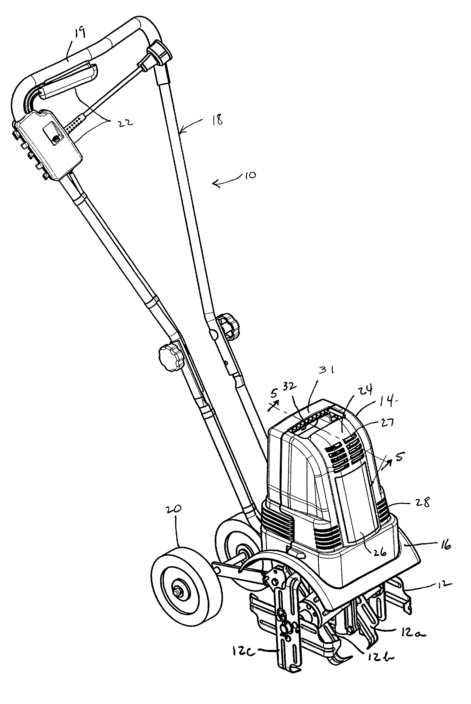
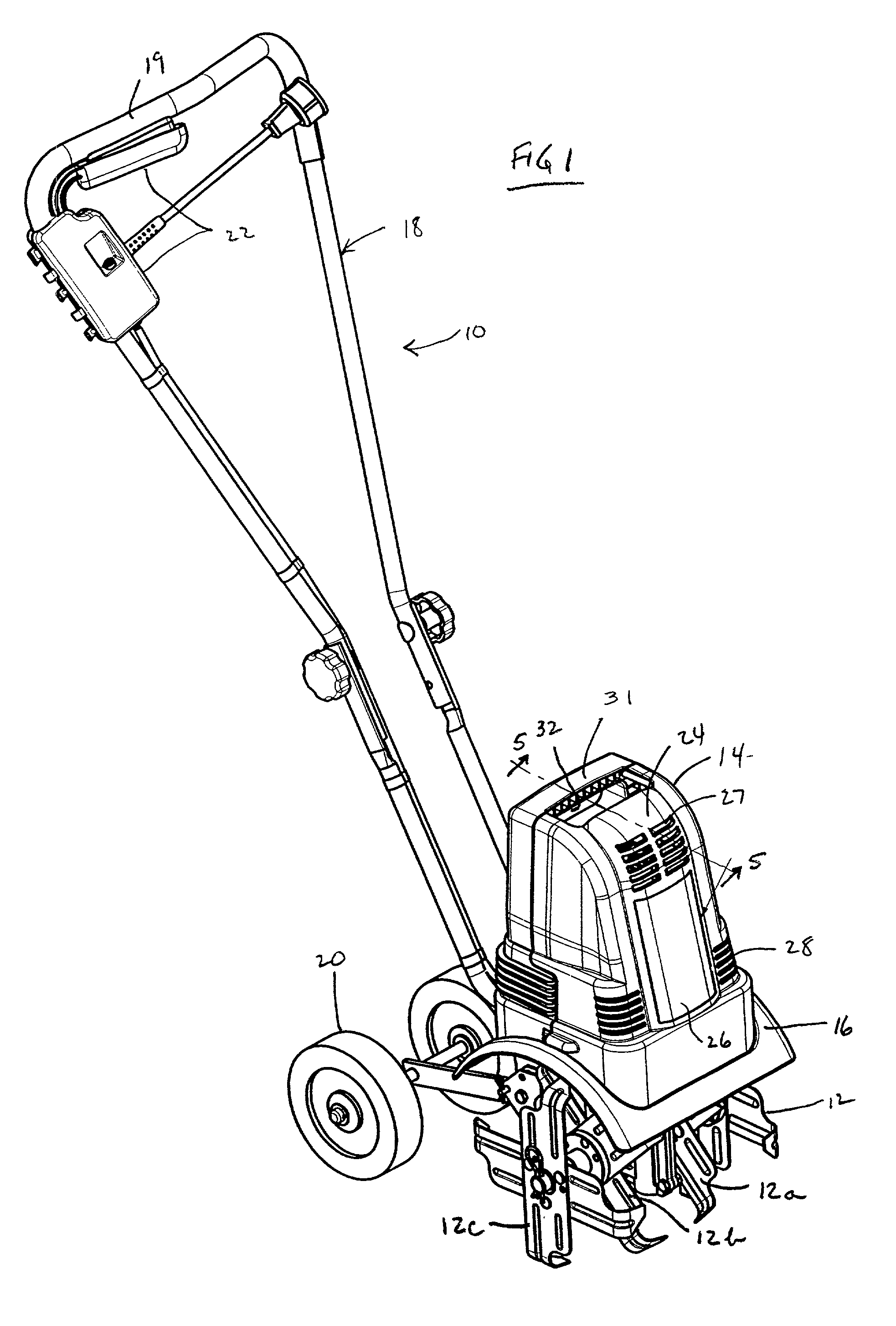
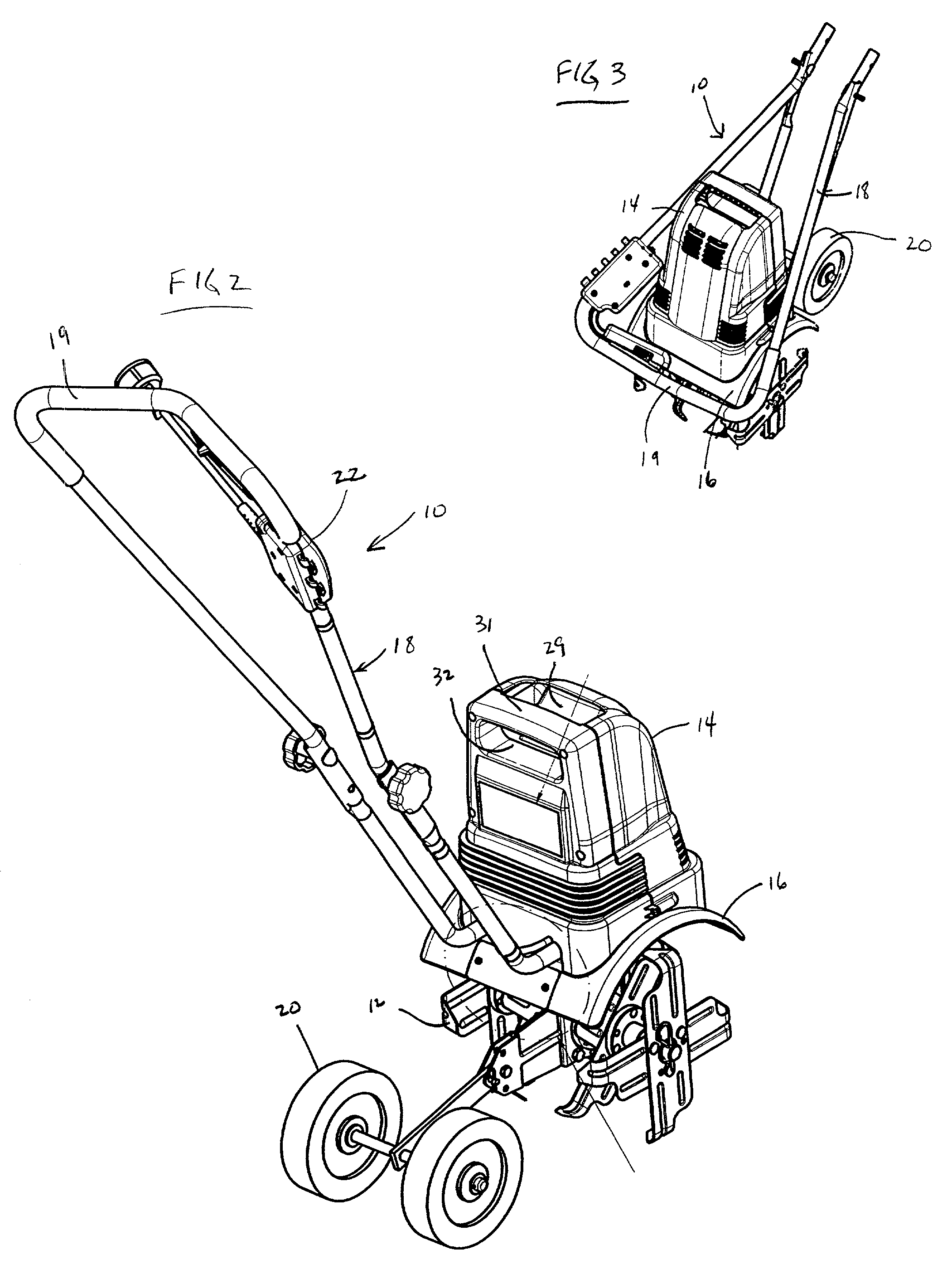
[0025]Referring now to FIGS. 1 and 2, there is illustrated the electric garden tiller 10 having four tine assemblies 12, 12a, 12b, 12c. These tines are driven by an electric motor which will be described below and which is covered by a main housing 14. Between the main housing 14 and the tines is a curved fender 16. Extending away from the tines is a handle 18 having a generally horizontal, padded, top portion 19 wh...


PUM


Abstract

An electric garden tiller is disclosed. The tiller is light weight, compact and easy to use. The tiller includes a two stage speed reduction transmission and an aluminum transmission housing. Connected to the transmission housing are a main housing and electric motor, a fender, a tine shaft and four tine assemblies, a rotatable wheel assembly and a foldable handle. Connected to the handle is a safety switch mechanism requiring two simultaneous actions to activate the motor. Once activated, if an operator's hand is removed, the motor will stop.

Description

BACKGROUND OF THE INVENTION[0001]1. Field of the Invention[0002]The present invention relates to an electric tiller and more particularly to an electric garden tiller which is lightweight, easy to use, quiet and pollution free.[0003]2. Description of the Related Art[0004]Consumer type tillers for use in gardens and the like are well known. For example, see U.S. Pat. Nos. 4,567,949; 5,251428; 5,896,931; and 6,092,608. These tillers include a gasoline powered internal combustion engine, a transmission, a tine shaft bearing a number of tines, an operating handle and a set of wheels. These products tended to be noisy, sources of pollution, heavy and difficult to use.[0005]The market has also seen electric rotary tillers, such as the POWER-TILL brand, sold by the assignee of the present application. These were quieter and non-polluting, however, they too tended to be heavy and somewhat difficult to use.[0006]Efforts are still being made, in spite of the numerous prior attempts, to provid...

Claims


Application Information

Patent Timeline
Patent Type & Authority Patents(United States)
IPC IPC(8): A01B33/00A01B33/02
CPCA01B33/028
Inventor ABENROTH, JON M. T.FISHER, DAVID B.
Owner MTD PRODUCTS
Why Eureka
Try Eureka