
Optometric apparatus

Active Publication Date: 2007-07-03
NIDEK CO LTD
View PDF10 Cites 5 Cited by
  • Summary
  • Abstract
  • Description
  • Claims
  • Application Information

AI Technical Summary

Benefits of technology

[0007]The present invention has been made in view of the above circumstances and has an object to overcome the above problems and to provide an optometric apparatus which allows a near vision examination to be performed with high precision as compared with a conventional optometric apparatus.

Problems solved by technology

The optometric apparatus provided with the above mentioned slide mechanism and convergence mechanism has such a disadvantage that when the right and left lens chamber units are moved closer and converged in order to adjust the optical axis of the optical element to the visual axis of an examinee whose pupillary distance is narrow (short), the lens chamber units are likely to come into contact with each other.
However, with this apparatus, the examinations could not be performed with high precision.

Method used


Image

  • Optometric apparatus
  • Optometric apparatus
  • Optometric apparatus

Examples


Embodiment Construction

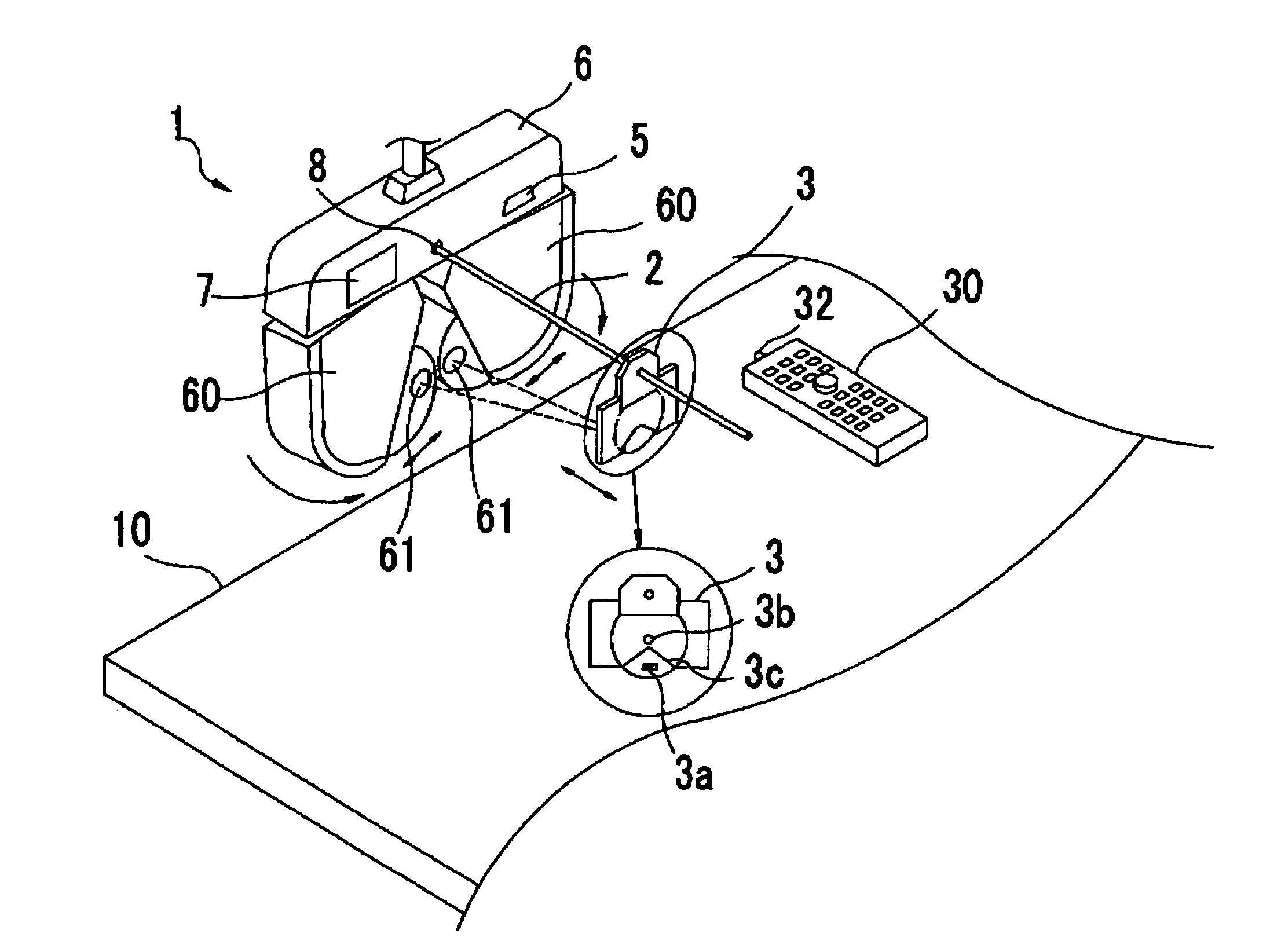
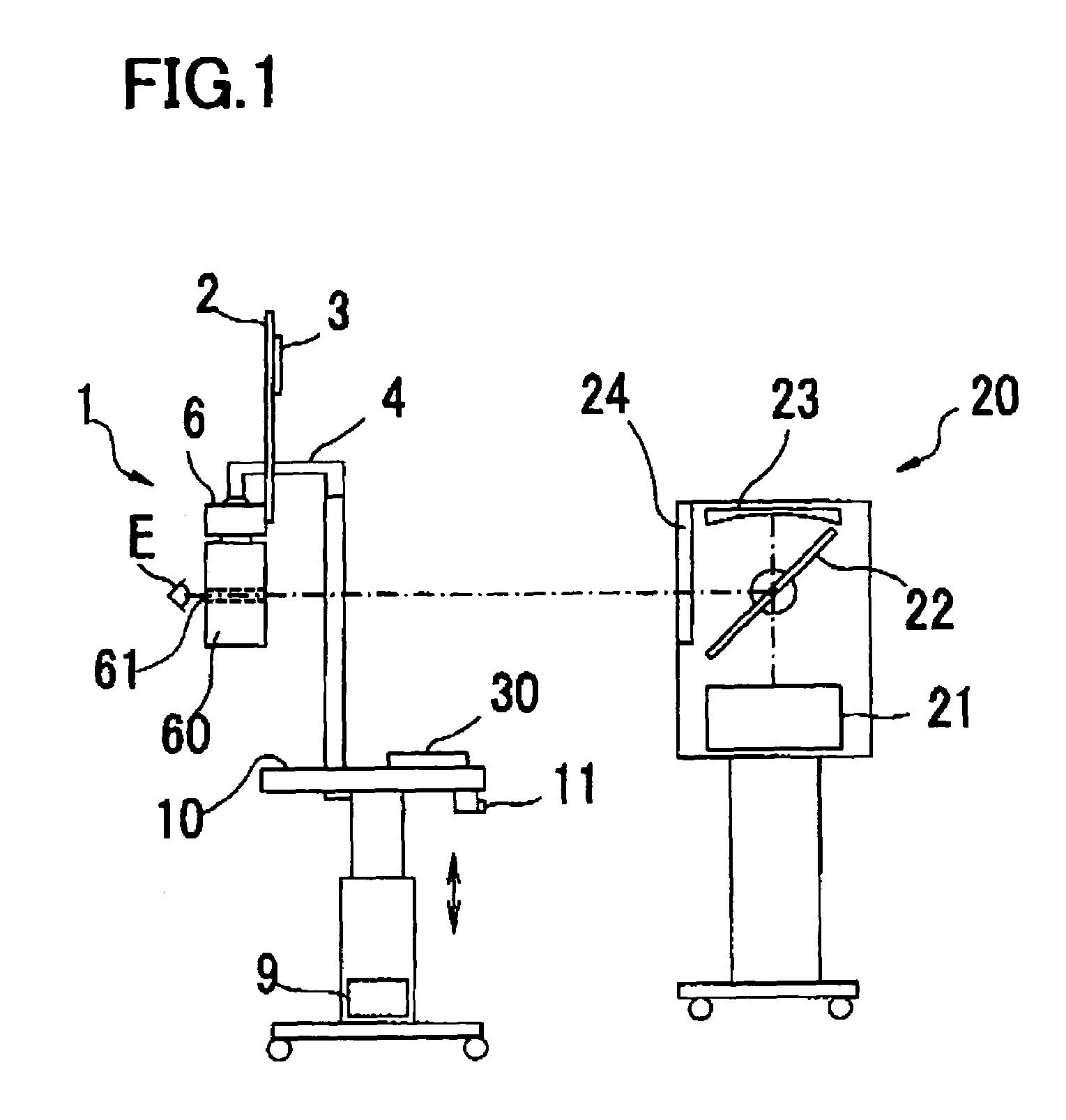
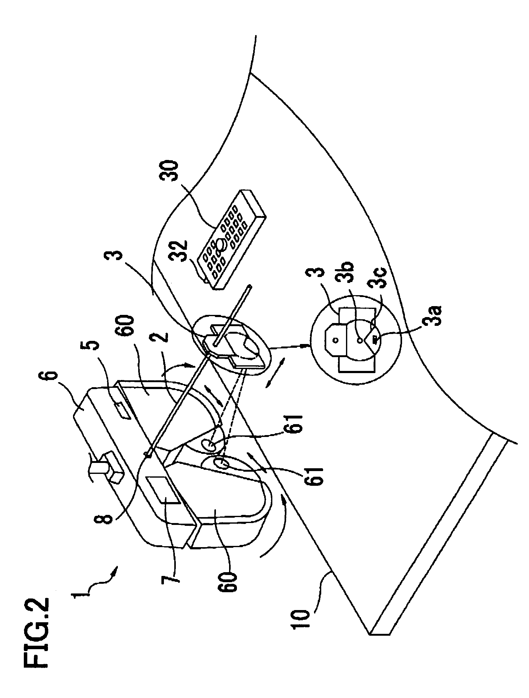
[0024]A detailed description of a preferred embodiment of the present invention will now be given referring to the accompanying drawings. FIG. 1 is a schematic structural view of an optometric system including an optometric apparatus in the present embodiment. FIGS. 2 and 3 are schematic structural views of the optometric apparatus seen from an operator side.

[0025]A main unit 1 of the optometric apparatus includes a pair of right and left lens chamber units 60 having symmetric shapes, each having a test window 61, and a movement unit 6 supporting (holding) the lens chamber units 60 in a hanging state. The movement unit 6 houses a movement mechanism 40 (see FIG. 5) including a slide mechanism for adjusting the interval between the right and left lens chamber units 60 and a convergence mechanism for adjusting a convergence angle (an inward directing angle) of the lens chamber units 60.

[0026]The main unit 1 is supported above a table 10 by a support arm 4 provided on the table 10. By o...


PUM


Abstract

An optometric apparatus comprises: a pair of right and left lens chamber units, each unit including a test window and optical elements to be selectively disposed in the test window; a convergence unit which converges the right and left lens chamber units; an input unit with which a pupillary distance of an examinee is inputted; a calculation unit which determines a convergence angle of the right and left lens chamber units based on a distance for a near vision examination at which a near vision optotype is presented and the inputted pupillary distance, the convergence angle for the inputted pupillary distance longer than a predetermined reference distance being determined such that an optical axis of the optical element is substantially aligned with a visual axis of an examinee's eye, whereas the convergence angle for the inputted papillary distance shorter than the reference distance being determined such that the right and left lens chamber units are converged without coming into contact with each other; and a control unit which controls driving of the convergence unit based on the determined convergence angle.

Description

BACKGROUND OF THE INVENTION[0001]1. Field of the Invention[0002]The present invention relates to an optometric apparatus for subjectively examining (measuring) a refractive power of an eye of an examinee.[0003]2. Description of Related Art[0004]There has been known an optometric apparatus constructed to subjectively examine (measure) a refractive power (a visual acuity) of an eye of an examinee by presenting optotypes forward of the eye through an optical element such as a spherical lens and cylindrical lens placed in front of the eye. Examinations using this type of optometric apparatus include a far vision examination in which optotypes are presented at a far vision examination distance of for example 5 m and a near vision examination in which optotypes are presented at a near vision examination distance of for example 35 cm.[0005]In the case of the near vision examination using the conventional optometric apparatus, a pair of lens chamber units for right and left eyes in each of ...

Claims


Application Information

Patent Timeline
IPC IPC(8): A61B3/02A61B3/028
CPCA61B3/0285A61B3/028
Inventor TERABE, HIROHISA
Owner NIDEK CO LTD
Learn More