Backlight unit having a cooling member

a cooling member and backlight technology, applied in the field of backlight units, can solve the problems of reduced luminescence efficiency of lamps 212/b>, failure to display images of desired quality, and high temperature, and achieve the effect of preventing luminescence efficiency

Active Publication Date: 2007-07-03
HANNSTAR DISPLAY CORPORATION
View PDF8 Cites 5 Cited by
  • Summary
  • Abstract
  • Description
  • Claims
  • Application Information

AI Technical Summary

Benefits of technology

[0013]In view of the problems in the conventional backlight units as described above, it is an object of the present invention to provide a backlight unit that solves the problems in the conventional backlight units. More specifically, it is an object of the present invention to provide a backlight unit that can radiate the heat generated from the light source while preventing the luminescence efficiency at the light-emitting surface from being degraded, even though the heat is not radiated from the rear side of the backlight unit.
[0015]In accordance with the backlight unit of the present invention, the cooling member radiates the heat generated by the lamp to improve the luminescence efficiency of the backlight unit without using the rear side of the backlight unit.

Problems solved by technology

Consequently, in the LCD device 200, the liquid crystal panel 202 may be heated up to an undesired temperature, particularly in a higher-temperature ambient, and may fail to display images of desired quality.
Thus, in the backlight unit 201, there is a problem in that the lamps 212 have a reduced luminescence efficiency when their operating temperature rises above the specific temperature, due to the heat they generate.

Method used


Image

  • Backlight unit having a cooling member
  • Backlight unit having a cooling member
  • Backlight unit having a cooling member

Examples


first embodiment

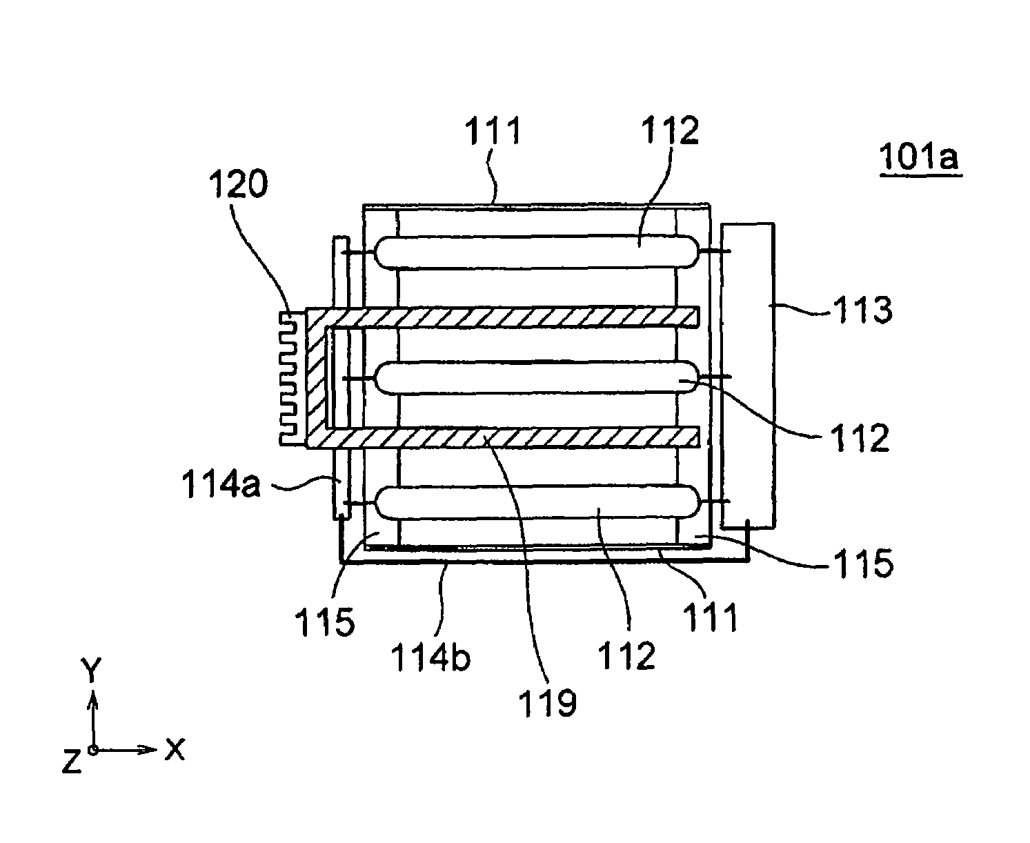
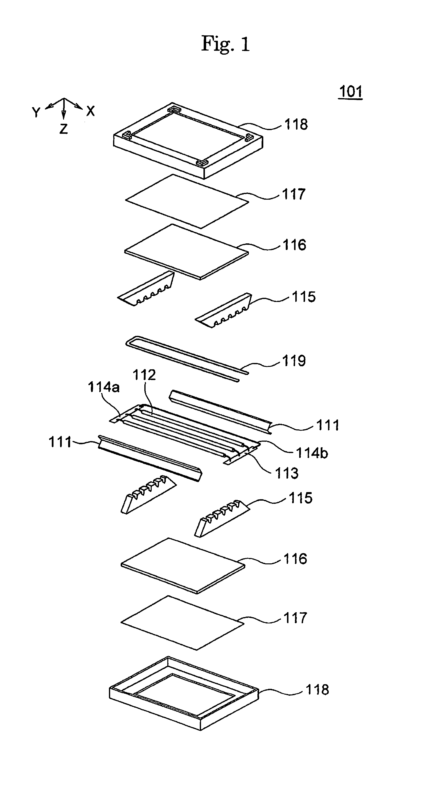
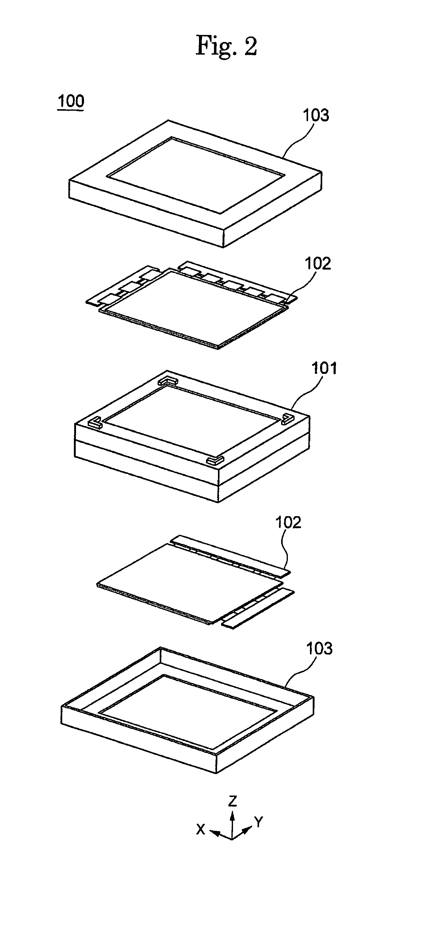
[0037]FIG. 1 is an exploded perspective view showing a double-surface backlight unit 101 according to the present invention. The double-surface backlight unit 101 includes a front part and a rear part, which are symmetrical with respect to lamps 112. Each of the front and rear parts has a lamp-supporting base 115, a diffusion plate 116, an optical sheet 117, and a backlight chassis 118. The double-surface backlight unit 101 differs from the conventional double-surface backlight unit 201a (FIG. 19) in that it has a heat-radiation member 119. The heat-radiation member 119 is used as a cooling device. FIG. 2 is an exploded perspective view of a LCD device 100 that includes the double-surface backlight unit 101. The LCD device 100 has a pair of liquid crystal panels 102 and a pair of front shields 103, in addition to the double-surface backlight unit 101. In the front and rear parts of the backlight unit 101, the front shield 103 holds the liquid crystal panel 102.

[0038]As shown FIG. 1,...

seventh embodiment

[0050]In most LCD devices having a one-side backlight unit, the X-direction drive circuit 204 and Y-direction drive circuit 205 are arranged at the rear side of the reflecting plate 111, as is illustrated in FIG. 18. In the seventh embodiment i.e., backlight unit 101f, the heat radiated from the reflecting plate 111 can be reduced. Thus, the LCD device that incorporates therein the backlight unit 101f does not involve a problem in that the X-direction drive circuit 204 and Y-direction drive circuit 205 are heated. In addition, since the heat radiated from the optical sheet 117 is also reduced, a malfunction involved with the heating of the liquid crystal panel 202 can be avoided.

[0051]The heat radiated from the lamp housing via the heat-radiation member 119 can be released into the atmosphere, as will be described hereinafter. In the case of the backlight unit that has the structure of FIG. 5, the heat sinks 120 provided at both the ends of the heat-radiation member 119 in the X-axi...


PUM

PropertyMeasurementUnit
AC voltageaaaaaaaaaa
light transmittanceaaaaaaaaaa
heat-absorbingaaaaaaaaaa

Abstract

A backlight unit includes a lamp housing, a plurality of elongate lamps received therein, and a cooling member having a heat-absorbing part and a heat-radiating part. The heat-absorbing part includes a plurality elongate heat-absorbing portions having a light reflecting function and arranged alternately with the elongate lamps. The heat-radiating part extends from the elongate heat-absorbing portions of the heat-absorbing part and is disposed outside the lamp housing. The cooling member has a heat-radiation function as well as a luminescence assistance function.

Description

BACKGROUND OF THE INVENTION[0001]1. Field of the Invention[0002]The present invention relates to a backlight unit of direct emission type in which light sources are arranged at the rear side of the light emitting surface of the backlight unit. The present invention also relates to a LCD device including such a backlight unit.[0003]2. Description of the Related Art[0004]Backlight units are known in the art as planar light-emitting devices. The backlight units are generally classified into two types. The first type is a direct emission unit, in which a plurality of light sources (i.e., lamps) are arranged at the rear side of the light-emitting surface of the backlight unit. The second type is an edge-light emission unit, in which the light emitted by the light sources is guided toward the light-emitting surface by an optical guide plate. The direct emission unit has a larger light-emitting surface and thus can attain a higher luminance, compared to the backlight unit of the edge-light...

Claims


Application Information

Patent Timeline
Patent Type & Authority Patents(United States)
IPC IPC(8): F21V29/00F21S2/00G02F1/1333F21V19/00F21V29/02G02F1/1335G02F1/13357
CPCF21V29/76G02F1/133604F21V29/004F21V29/30F21V29/56F21V29/70B60C11/0041B60C9/0042B60C9/1807B60C9/0007B29D30/52
Inventor ONO, SHIN-ICHIROU
Owner HANNSTAR DISPLAY CORPORATION
Why Eureka
Try Eureka