Light source cooling structure

A heat dissipation structure and light source technology, which is applied in the direction of electrical components, circuits, semiconductor devices, etc., can solve the problems affecting the service life of LEDs, the light decay of LEDs, and the efficiency of lighting, so as to maintain the service life, reduce the impact, increase The effect of heat dissipation cross-sectional area

Inactive Publication Date: 2016-05-25
周焕球
View PDF6 Cites 0 Cited by
  • Summary
  • Abstract
  • Description
  • Claims
  • Application Information

AI Technical Summary

Problems solved by technology

[0003] However, in the process of driving the light emitting diode, the light emitting diode will generate high heat energy, and this heat energy will not only affect the service life of the light emitting diode, but also affect the efficiency of light emission, so that the light emitting diode will have the phenomenon of light decay
[0004] In order to solve the above-mentioned defects, many heat dissipation structures for eliminating the heat energy generated by the light-emitting diodes have been proposed in traditional methods, but the above-mentioned heat dissipation structures can only allow lower-power light-emitting diodes to obtain better heat dissipation. , there will still be traditional defects

Method used


Image

  • Light source cooling structure
  • Light source cooling structure
  • Light source cooling structure

Examples


Embodiment 1

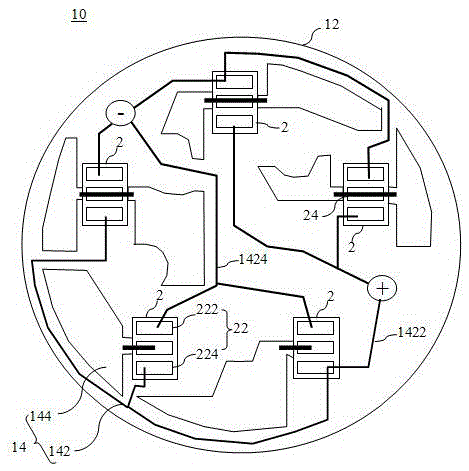
[0040] figure 1 It is a schematic layout diagram of the heat dissipation structure of the light source in Embodiment 1 of the present invention. Such as figure 1 As shown, the light source heat dissipation structure 10 can dissipate heat energy generated when the light source 2 (such as a light emitting diode) emits light. Wherein, the bottom of the light source 2 generally has an electrical contact 22 of at least one of the positive end 222 and the negative end 224 , and a heat dissipation contact 24 . The electrical contact 22 can obtain the power supply PW required to drive the light source 2 to emit light from a transformer, commercial power, primary battery or secondary battery. In another embodiment, the negative end 224 of the light source 2 may replace the heat dissipation contact 24 , so that the light source only has the positive end 222 and the negative end 224 .

[0041] The light source heat dissipation structure 10 includes a heat dissipation substrate 12 , a ...

Embodiment 2

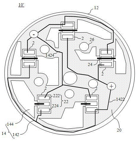
[0050] image 3 It is a schematic layout diagram of the heat dissipation structure of the light source in Embodiment 2 of the present invention. image 3 Among them, the light source heat dissipation structure 10' can also dissipate the heat energy generated when the light source 2 emits light, and the light source heat dissipation structure 10' includes the heat dissipation substrate 12, the layout layer 14 and the heat dissipation diffusion layer 16 in Embodiment 1. In addition, it also includes an insulating layer 18 , a heat dissipation coating layer 20 and a hole 26 .

[0051] Wherein, the insulating layer 18 is formed between the heat dissipation substrate 12 and the layout layer 14 to block the electrical conduction between the heat dissipation substrate 12 and the layout layer 14 . It should be noted that the insulating layer 18 is not an essential part. For example, if the heat dissipation substrate 12 is made of non-metallic material, the insulating layer 18 is not...


PUM


Abstract

The invention relates to a heat dissipation structure of a light source. The light source heat dissipation structure includes a light source, the light source has electrical contacts and heat dissipation contacts, the light source heat dissipation structure includes a heat dissipation substrate; a layout layer is formed on one side of the heat dissipation substrate, and the layout layer has electrical layout lines and The heat dissipation layout line, the electrical layout line is connected to the electrical contact, and the heat dissipation layout line is connected to the heat dissipation contact, wherein no electrical wiring is formed between the electrical layout line and the heat dissipation layout line. connection; and a heat dissipation diffusion layer formed on the heat dissipation layout line, the heat dissipation diffusion layer having a thickness. The invention can not only reduce the waste of copper foil in the process of layout etching, but also accelerate the removal of heat energy by increasing the heat dissipation cross-sectional area for dissipating heat energy.

Description

technical field [0001] The invention relates to a heat dissipation structure of a light source, in particular to a light source heat dissipation structure that provides high heat energy generated by the light source to dissipate quickly, maintains the service life of the light source and reduces light attenuation of the light source. Background technique [0002] In the prior art, due to the advantage of long service life of light-emitting diodes, light-emitting diodes replace traditional light sources such as old tungsten bulbs to achieve the effect of energy saving and carbon reduction. [0003] However, in the process of driving the light emitting diode, the light emitting diode will generate high heat energy, and this heat energy will not only affect the service life of the light emitting diode, but also affect the efficiency of light emission, so that the light emitting diode will have the phenomenon of light decay . [0004] In order to solve the above-mentioned defec...

Claims


Application Information

Patent Timeline
Patent Type & Authority Patents(China)
IPC IPC(8): H01L33/64H01L33/62
CPCH05K1/0209H05K1/181H05K2201/10106
Inventor 周焕球
Owner 周焕球
Why Eureka
Try Eureka