Superconductive device comprising a refrigeration unit, equipped with a refrigeration head that is thermally coupled to a rotating superconductive winding

a superconductive winding and refrigeration unit technology, applied in the direction of indirect heat exchangers, lighting and heating apparatus, domestic cooling devices, etc., can solve the problems of affecting the operation of the conventional valve drive mechanism, and affecting the operation of the refrigeration unit. , to achieve the effect of reducing equipment costs and reliable and cost-effective operation

Inactive Publication Date: 2007-07-10
SIEMENS AG
View PDF13 Cites 5 Cited by
  • Summary
  • Abstract
  • Description
  • Claims
  • Application Information

AI Technical Summary

Benefits of technology

[0007]The object of the present invention is to configure the device with the features stated in the introduction, proceeding from this state of the art, in such a way that it can ensure reliable and cost-effective operation of the refrigeration unit both in the cooling phase and also in the stationary state and in the case of rotation of the rotor in a temperature range below 77 K and with a reduced equipment cost by comparison.
[0016]In the case of the superconductive device according to the invention, therefore, two different cooling methods are combined. A first method, which represents pure thermosyphon cooling, provides a working gas as a first coolant for the purposes of cooling during the operating phase. Only in conjunction with this first method of convective cooling can further thermosyphons with other gases (i.e. with at least one further coolant), and therefore other working temperatures, be simultaneously thermally coupled to the parts of the rotor to be cooled (=further method). This enables effective and inexpensive precooling in the presence of optimum exploitation of the refrigeration power of the refrigeration head.
[0017]Further advantages of the configuration of the superconductive device according to the invention can be seen in the fact, among others, that no moving parts such as fans or pumps, for example, are required for recirculating the coolant. Additionally, the refrigeration unit can be easily adapted to the different requirements of a machine installation. In particular, thermal tubes several meters long can be provided depending on the design, with the result that, for example, a refrigeration machine can be mounted in an accessible place to facilitate its maintenance while the actual motor or generator is installed in a manner that is difficult to access. The thermal transfer or the provision of the refrigeration power is therefore particularly simple and cost-effective in the case of the configuration according to the invention.
[0020]Furthermore, particularly simple sealing of the coolant chamber can be achieved as a result of the fact that the central cavity is closed by the winding support on one side and the lateral cavity is sealed by a sealing device with co-rotating parts on the side facing the refrigeration head. In this respect, at least one seal in the category ferrofluid seal, labyrinth seal, diaphragm gland can preferably be considered for the sealing device.

Problems solved by technology

It has been found, however, that conductors known to date only possess a relatively low current carrying capacity in magnetic fields with inductions in the tesla range.
Additionally, the accessibility of the co-rotating parts of the refrigeration unit and in particular of the valve drive mechanism in the rotor of the machine is hampered since the rotor housing must be opened in the case of maintenance being required.
Furthermore, the function of a conventional valve drive mechanism is not assured in the case of rapid rotation such as is present in the case of synchronous motors or generators.

Method used


Image

  • Superconductive device comprising a refrigeration unit, equipped with a refrigeration head that is thermally coupled to a rotating superconductive winding
  • Superconductive device comprising a refrigeration unit, equipped with a refrigeration head that is thermally coupled to a rotating superconductive winding
  • Superconductive device comprising a refrigeration unit, equipped with a refrigeration head that is thermally coupled to a rotating superconductive winding

Examples


Embodiment Construction

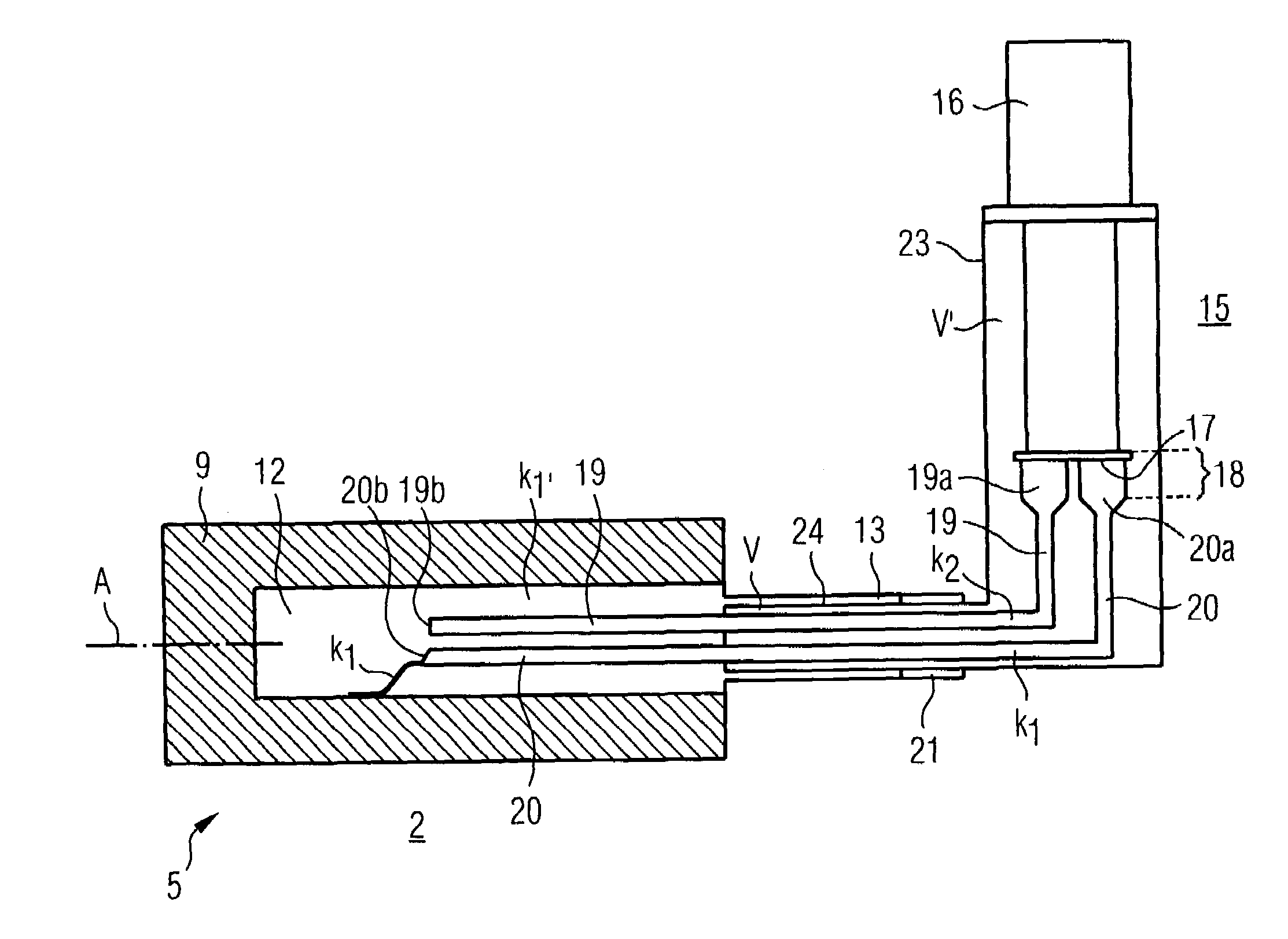
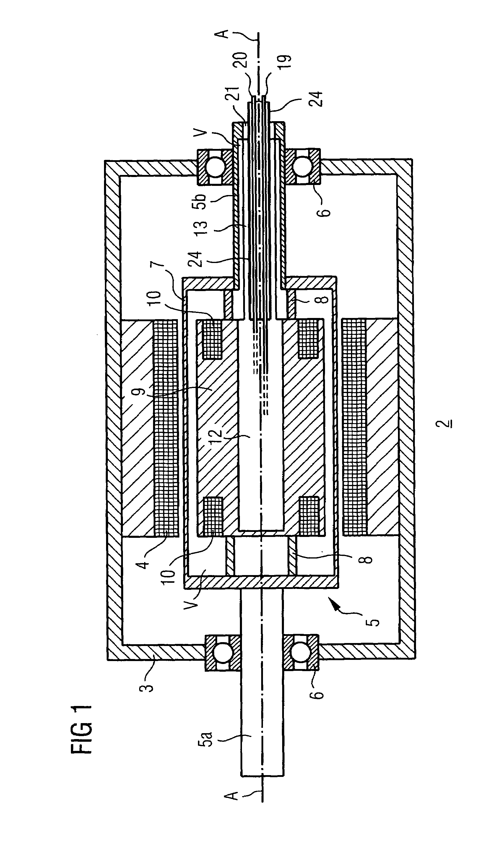
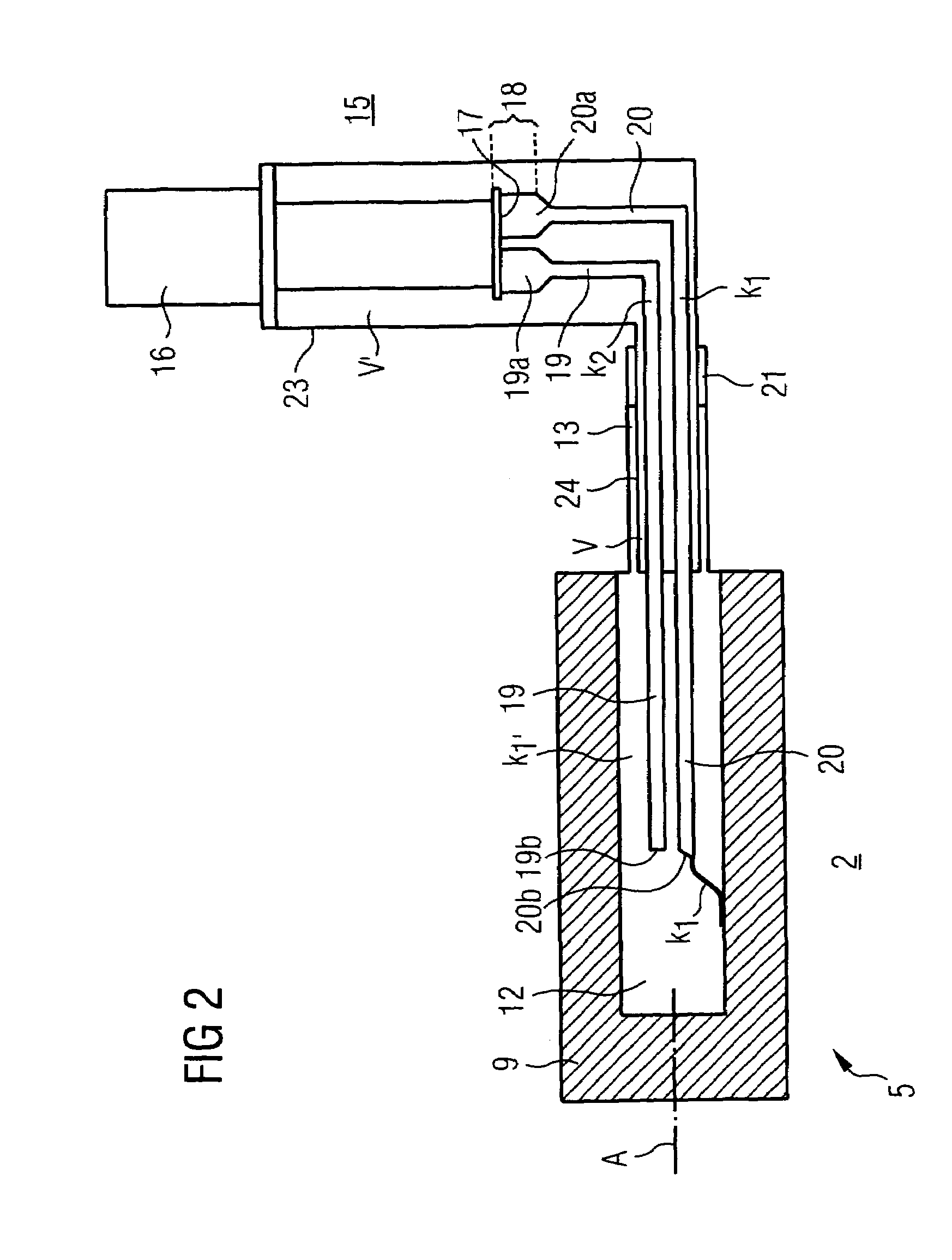
[0031]The embodiments of superconductive devices according to the invention highlighted on the basis of the diagrams in the following can constitute a (synchronous) motor or a (synchronous) generator in particular in each case. The superconductive device comprises a rotating superconductive winding, which in principle permits the use of metallic LTS material (low Tc superconductive material) or oxidic HTS material (high Tc superconductive material). MgB2 can also be considered as a superconductive material. For the following exemplary embodiments, let an HTS material such as the known (Bi,Pb)2Sr2Ca2Cu3Ox, for example, be selected. The winding can consist of a coil or a system of coils in a 2-pole, 4-pole or other multipole arrangement. The outline structure of the parts of such a superconductive device forming a synchronous machine, for example, that are situated in the area of the rotor, can be seen in FIG. 1, which is based on known embodiments of such machines (cf. the said U.S. ...


PUM


Abstract

The invention relates to a superconductive device containing a rotor that can be rotated about an axis of rotation and that comprises a superconductive winding in a winding support. Said winding support has a central cavity, into which two fixed thermal tubes project axially. One of said tubes forms a cooling finger that is closed at the end and contains a second coolant with a higher condensation temperature. The other tube supplies a first cooling with a lower condensation temperature to the central cavity and evacuates said coolant from the cavity. To condense the coolants, the tubes lead to a refrigeration unit, situated outside the rotor and equipped with a refrigeration head and a condenser device.

Description

CROSS REFERENCE TO RELATED APPLICATION[0001]This application is the US National Stage of International Application No. PCT / DE03 / 01052, filed Mar. 31, 2003 and claims the benefit thereof. The International Application claims the benefits of German Patent application No. 10221635.5 DE filed May 15, 2002, both of the applications are incorporated by reference herein in their entirety.FIELD OF THE INVENTION[0002]The invention relates to a superconductive device with a rotor which is mounted so that it can be rotated about an axis of rotation and which displays at least one superconductive winding, the conductors of which are arranged in a winding support, and with a refrigeration unit which displays at least one refrigeration head that is thermally coupled to the winding. A corresponding device is disclosed by U.S. Pat. No. 5,482,919 A.BACKGROUND OF THE INVENTION[0003]In addition to the long familiar metallic superconductive materials such as NbTi or Nb3Sn, which have very low transitio...

Claims


Application Information

Patent Timeline
Patent Type & Authority Patents(United States)
IPC IPC(8): F25B19/00F25B9/00F28D15/00F28D15/02F25D19/00H02K55/04
CPCF25D19/006F28D15/0266H02K55/04Y02E40/625Y02E40/60
Inventor FRANK, MICHAELNICK, WOLFGANGVAN HASSELT, PETER
Owner SIEMENS AG
Why Eureka
Try Eureka