Method for determining the temperature of a battery

a battery and temperature technology, applied in the field of methods for determining the temperature of batteries, can solve the problems of comparatively large damage and further damage, and achieve the effect of reliably determined, easy implementation, and easy creation

Active Publication Date: 2017-11-14
ROBERT BOSCH GMBH
View PDF18 Cites 1 Cited by
  • Summary
  • Abstract
  • Description
  • Claims
  • Application Information

AI Technical Summary

Benefits of technology

[0012]Such a case of failure, as this is generally known, can particularly take place inside of the battery cell and, in so doing, proceed in a plurality of steps, wherein each of the elapsing steps can cause comparatively large damage. If overheating occurs, damage or a breakdown can, for example, occur to an electrolyte layer disposed on the anode or respectively to a protective layer disposed between electrolyte and anode, whereby electrolyte constituents comprising anode materials, such as, for example, carbon, can react exothermically, which can further increase the temperature of the cell. In so doing, such exothermal processes, for example the processes taking place on the anode, can further accelerate, wherein the heat produced in this manner can decompose somewhat organic solvents, which, for example, may be present in the electrolyte. This can in turn lead to inflammable gases, such as, for example, ethane, methane or other hydrocarbons being able to be released. The development of such gases as a result of the decomposition of the electrolyte, can, for example, further cause a pressure increase in the interior of the cell, which can cause further damage.
[0039]The previously described battery system allows the temperature of a battery cell or respectively the battery to be determined in a particularly simple and cost effective manner and in so doing in a particularly precise manner. Along with this, a particularly cost effective and reliable operation and furthermore a particularly long service life of the battery is assured.

Problems solved by technology

Such a case of failure, as this is generally known, can particularly take place inside of the battery cell and, in so doing, proceed in a plurality of steps, wherein each of the elapsing steps can cause comparatively large damage.
The development of such gases as a result of the decomposition of the electrolyte, can, for example, further cause a pressure increase in the interior of the cell, which can cause further damage.

Method used


Image

  • Method for determining the temperature of a battery
  • Method for determining the temperature of a battery

Examples


Embodiment Construction

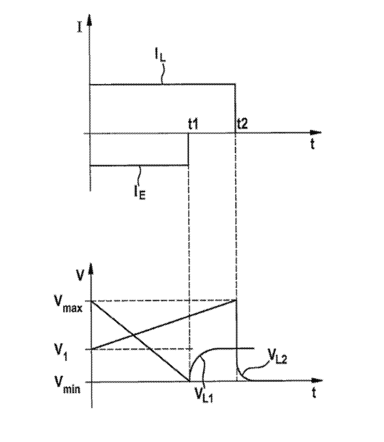
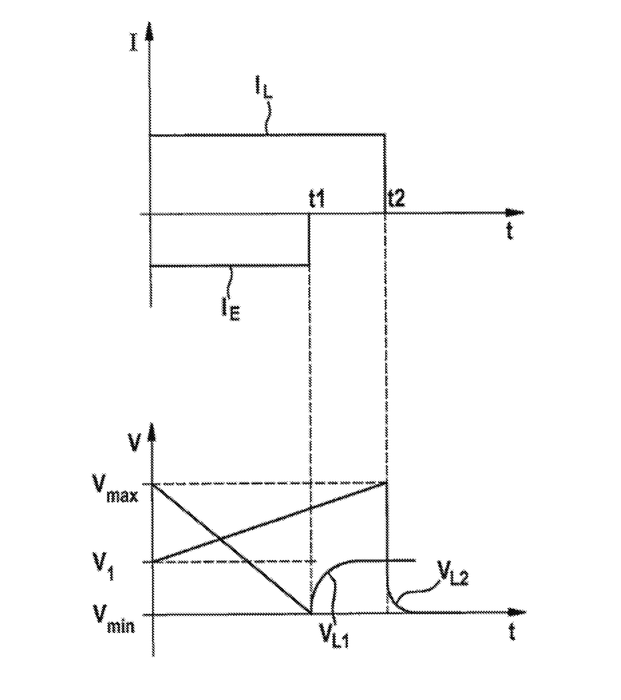
[0043]A diagram is shown in FIG. 1, which shows the change in the open-circuit voltage VL1, VL2 (lower region) after the end of the flow of a current IL, IE (upper region) at a given temperature and a given state of charge of a battery, such as, for example, a lithium-ion battery.

[0044]The diagram of FIG. 1 shows in detail the profile of the voltage V and the current I versus the time t. It can thereby be seen that if a charging process (charge current IL) or also a discharging process (discharge current IE) is ended approximately at the times t1 or t2, a change in the open-circuit voltage VL1, VL2 can be determined as a function of the time at all of the values of the state of charge. In reference to FIG. 1, a discharge current IE is used for a period of time up to a point in time t1, wherein a drop in the voltage V occurs, and in fact from a maximum voltage Vmax to a minimum voltage Vmin. A disconnection of the cell and therefore the end of the flow of the discharge current IE at ...


PUM

PropertyMeasurementUnit
temperatureaaaaaaaaaa
state of chargeaaaaaaaaaa
open-circuit voltageaaaaaaaaaa

Abstract

The invention relates to a method for determining the temperature of a battery, comprising the following steps: a) determining the state of charge of at least one battery cell; b) determining a change in the open-circuit voltage (VL1, VL2) of the at least one battery cell immediately after the end of the flow of an electric current (IL, IE) through the at least one battery cell; and c) determining the temperature of the at least one battery cell on the basis of the state of charge and the change in the open-circuit voltage (VL1, VL2). The method described above economically enables especially reliable operation of the battery that is stable over the long term.

Description

BACKGROUND OF THE INVENTION[0001]The present invention relates to a method for determining the temperature of a battery. The invention relates particularly to a method for determining the temperature with improved accuracy by precisely determining the cell temperature.[0002]Electrochemical energy stores, such as, for example, lithium-ion batteries, are widely used in many daily applications. Said electrochemical energy stores are, for example, used in computers, such as laptops, mobile telephones, smartphones and other applications. Such batteries also offer advantages in the electrification of vehicles, such as motor vehicles, which is presently being greatly advanced.[0003]The operating temperature of batteries respectively of battery cells is often an important operating parameter. For example, the temperature can have a great influence on the efficiency and durability of the battery because the efficiency and durability of the batteries can be reduced when temperatures are incre...

Claims


Application Information

Patent Timeline
Patent Type & Authority Patents(United States)
IPC IPC(8): G01K13/00H01M10/48G01R31/36H01M10/0525H01M10/052
CPCH01M10/486G01K13/00G01R31/362H01M10/48H01M10/0525H01M2220/20H01M10/052G01R31/3835Y02E60/10
Inventor REITZLE, ALEXANDERHORE, SARMIMALA
Owner ROBERT BOSCH GMBH
Why Eureka
Try Eureka