Method for determining the temperature of a battery
- Summary
- Abstract
- Description
- Claims
- Application Information
AI Technical Summary
Benefits of technology
Problems solved by technology
Method used
Image
Examples
Embodiment Construction
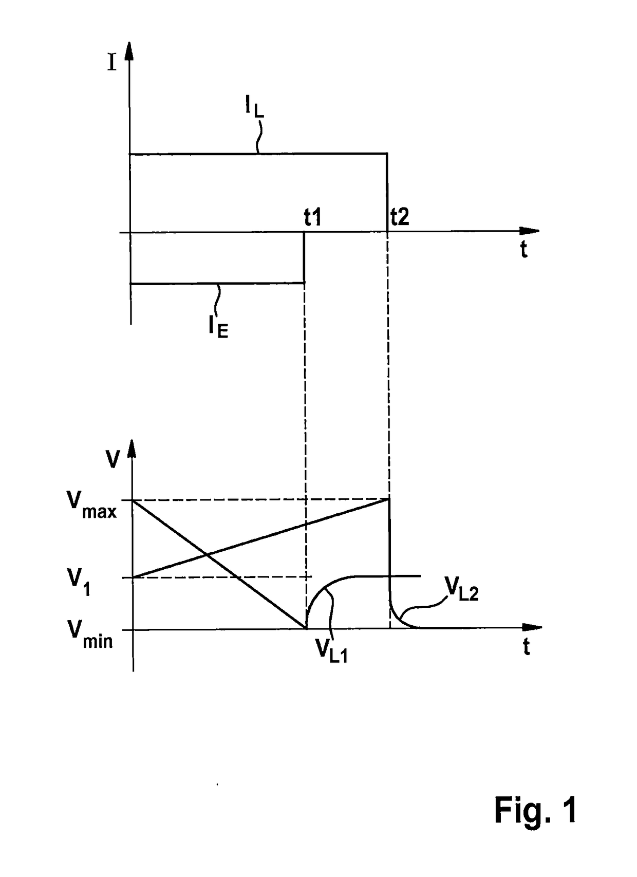
[0043]A diagram is shown in FIG. 1, which shows the change in the open-circuit voltage VL1, VL2 (lower region) after the end of the flow of a current IL, IE (upper region) at a given temperature and a given state of charge of a battery, such as, for example, a lithium-ion battery.
[0044]The diagram of FIG. 1 shows in detail the profile of the voltage V and the current I versus the time t. It can thereby be seen that if a charging process (charge current IL) or also a discharging process (discharge current IE) is ended approximately at the times t1 or t2, a change in the open-circuit voltage VL1, VL2 can be determined as a function of the time at all of the values of the state of charge. In reference to FIG. 1, a discharge current IE is used for a period of time up to a point in time t1, wherein a drop in the voltage V occurs, and in fact from a maximum voltage Vmax to a minimum voltage Vmin. A disconnection of the cell and therefore the end of the flow of the discharge current IE at ...
PUM
 Abstract
Description
Claims
Application Information
 - R&D
- Intellectual Property
- Life Sciences
- Materials
- Tech Scout
- Unparalleled Data Quality
- Higher Quality Content
- 60% Fewer Hallucinations
Browse by: Latest US Patents, China's latest patents, Technical Efficacy Thesaurus, Application Domain, Technology Topic, Popular Technical Reports.
© 2025 PatSnap. All rights reserved.Legal|Privacy policy|Modern Slavery Act Transparency Statement|Sitemap|About US| Contact US: help@patsnap.com

