Full contact floating roof

a floating roof and full contact technology, applied in the direction of packaging, containers, building components, etc., can solve the problems of inability to eliminate such losses, inability to achieve absolute elimination of losses, and limited engineering and practicality of full contact roof types, so as to improve fire suppression, improve fire protection, and suppress fire

Inactive Publication Date: 2007-07-10
HMT LIMITED
View PDF13 Cites 12 Cited by
  • Summary
  • Abstract
  • Description
  • Claims
  • Application Information

AI Technical Summary

Benefits of technology

[0013]In the preferred embodiment, each cell is extruded with a gripping slot on each side (as used herein, the cell's “bottom” is considered to be that side of the cell in contact with the contained fluid, the cell's “top” is that portion of the cell exposed to the open air or other atmosphere above the contained fluid, and the cell's “sides” are the sections of the cells which can be joined to other cells), into which can be inserted a formed, rigid or semi-rigid strip which, when inserted into the gripping slots of two of the cells, will maintain the sides of those cells in close proximity to each other and without allowing substantial relative movement of the cells. Additionally, it is preferred that an adhesive sealant, glue, or epoxy, such as Pliogrip (Ashland Chemical) is applied to the side surfaces of each two cells being joined, so that the final join between the cells will both be strong and provide a sufficient seal to prevent the escape of contained fluid or vapor from the bottom of the cells.
[0016]Constructed in this manner, each sub-cell provides an independent flotation device. Further, the individual sub-cells can be flooded with gas, such as an inert gas, to improve fire protection when the floating roof is used to contain volatile hydrocarbons. This process may be accomplished economically by inserting a valve or a selectively pluggable coupling through the top of each sub-cell. Moreover, a self-activating sealant or intumescent material such as Contega or Flameseal, for example, can be used to coat the interior of the sub-cells prior to sealing them, so that in the event of a fire above the roof, the individual sub-cells will close off and aid in preventing the fire from reaching the contained fluid. Alternatively, inserts coated with such materials can be inserted in the sub-cells. Similarly, in the event of a puncture of the roof and subsequent fire, the intumescent material can act to expand and seal the hole, thereby suppressing the fire if it has reached the contained fluid. a puncture of the roof and subsequent fire, the intermescent material can act to expand and seal the hole, thereby suppressing the fire if it has reached the contained fluid.
[0017]Thus, this floating roof provides a variety of advantages over other such roofs. Because the extruded materials are relatively lightweight and can be shipped as individual cells, or pre-assembled into sectional panels to be assembled on-site into a single roof, the cost and complexity of construction assembly on-site is greatly reduced. Further, the manner of construction, involving simple mechanical tools and adhesives, greatly reduces the need for skilled labor on site, as is required to weld steel sections together or to assemble complex, bolted, aluminum frameworks. Moreover, the extruded materials provide further advantages, because they are extremely corrosion resistant and therefore provide cost savings for long-term maintenance of the roof once it is installed.
[0018]The modular nature of the buoyant cells further allows each section to be tested for internal fluid or vapor leaks by providing signal communication between a fluid or vapor detection device internal to the cell and a monitor outside the cell. Detectors can be placed within each sub-cell, and connected together by drilling or cutting through the riser wall to allow a signal coupler, such as a wire or cable, to be passed between sub-cells. The integrity of the sub-cells can be restored by gluing a seal in place around the signal coupler where it passes through the riser. Alternatively, test ports can be inserted in any sub-cell through the external skin of a buoyant cell, sealed in place, and connected to an external detection device to test the sub-cell for fluid or vapor leaks.
[0019]Because holes from the top to the bottom of an extruded panel can be sealed off from the remainder of the sub-cell or sub-cells though which the hole passes by means of seals and adhesives, it is also relatively easy to provide drains or manholes through a buoyant cell, allowing rainwater or other fluid to be drained away and allowing for inspection of the region under the floating roof.

Problems solved by technology

However, such pontoon-floated roofs leave a vapor space above the liquid surface in the tank.
However, there will be losses of the liquid stored in the tank, as vapor leaks through seams in the roof or around seals.
Engineering of floating roofs attempts to eliminate such leakage losses, but the existence of a relatively volatile vapor space immediately under the roof makes absolute elimination of such losses impossible.
However, these types of full contact roofs have engineering and practicality limitations.
Current full contact roof designs are only marginally capable of sustaining the loads imposed on the structures.
They are also easily upset and sunk if there is a large operations anomaly in the underlying tank.
Because these roofs have to be constructed in the field, there are high labor and heavy-equipment machinery costs associated with assembling and moving materials around at the construction site.
Further, steel roofs require periodic repainting and are very susceptible to corrosion, creating high maintenance costs and potentially limiting the useful life of the roof.
A further limitation of the aluminum honeycomb or foam core sandwiched-panel type roofs is the inability to test the individual honeycomb cells for the presence of a foreign or combustible vapor.
Such vapor may be present if there is a leak in the outer sheeting cover.
Moreover, the aluminum honeycomb or foam core sandwiched panels are normally joined to the outer aluminum sheeting cover with glue or adhesive that frequently becomes brittle and inflexible after being applied.
Cyclic operation of the floating roof, or certain external loading conditions on the outer sheeting cover, such as walking on the roof, often cause theis glue or adhesive to crack, forming vapor or liquid paths between the individual compartments.
Thus, the leak-tight integrity of the individual compartments may be compromised.

Method used


Image

  • Full contact floating roof
  • Full contact floating roof
  • Full contact floating roof

Examples


Embodiment Construction

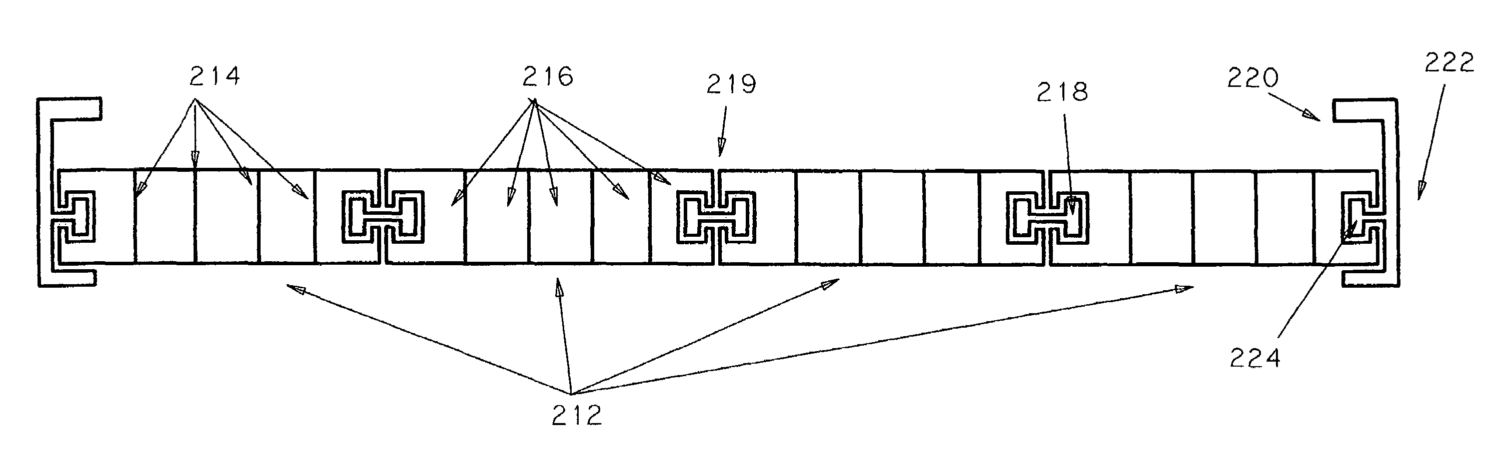
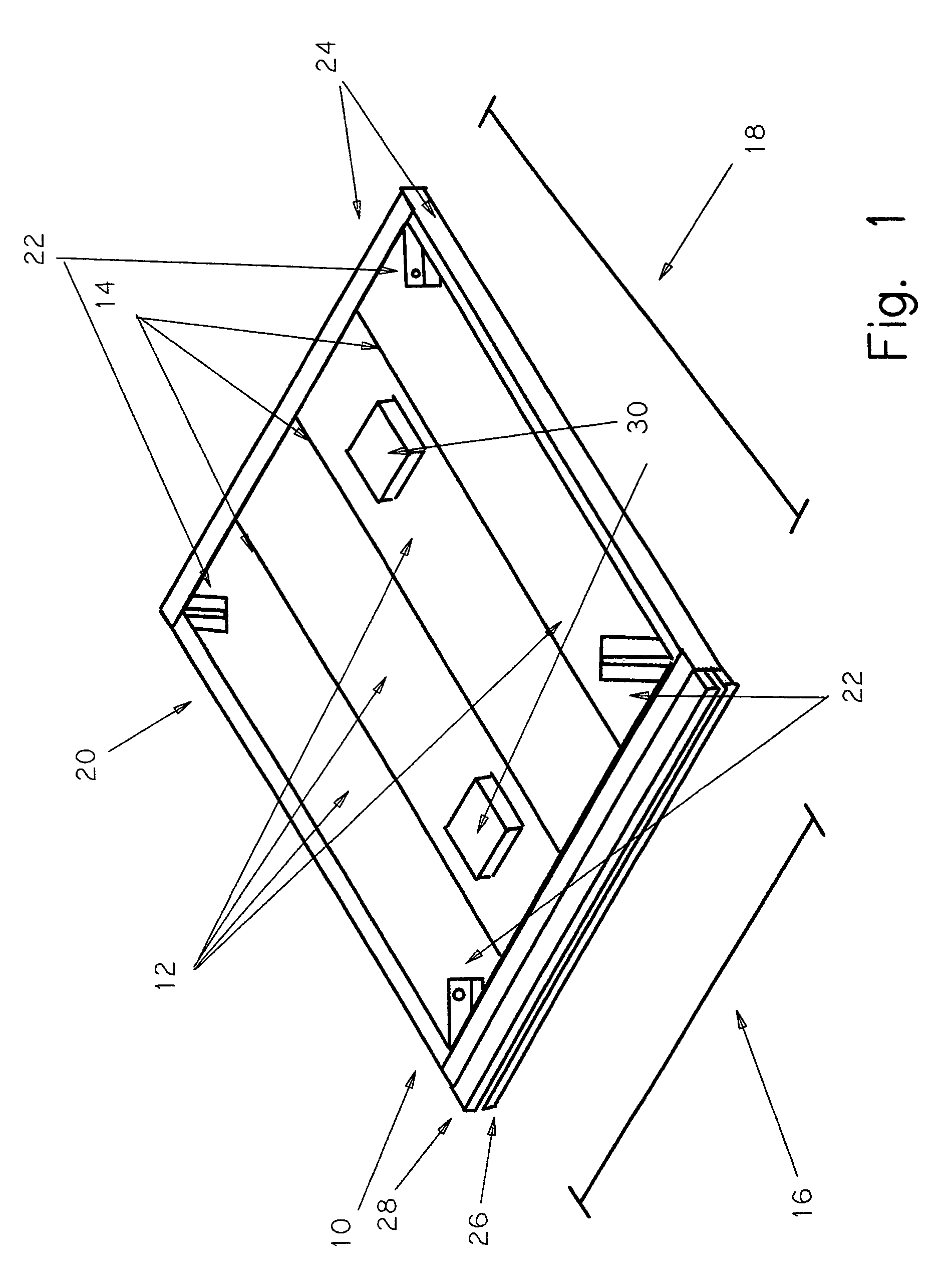
[0029]Referring to FIG. 1, a subsection 10 of a full contact floating roof of the present invention is shown. The subsection 10 is comprised of four square angle parallelepiped buoyant cells 12, which are joined together by joins 14. Thus, the width 16 of the subsection 10 will be essentially four times the width of each buoyant cell 12, and the length 18 will be essentially the length to which the buoyant cells have been cut. Because it may be convenient to pre-assemble subsections 10 away from the final construction site, the length 18 of the buoyant cells 12 can be determined by factors such as total weight of the subsection 10, shipping size limitations, or the dimensions of the overall roof to be constructed.

[0030]In the preferred embodiment, the subsection 10 is provided with a frame 20 which around the perimeter of the subsection 10, allowing for increased structural integrity for the subsection 10, and allowing for easy attachment of lift points 22 to the subsection 10. If o...


PUM


Abstract

A device and method of making a full contact floating roof for use in covering fluid bodies, such as storage tanks containing hydrocarbon fluids, allowing ease of construction, high integrity, and low maintenance cost.

Description

CONTINUATION APPLICATION[0001]This application is a continuation of U.S. patent application Ser. No. 10 / 397719, filed Mar. 26, 2003 now abandoned.TECHNICAL FIELD[0002]The invention concerns a device for covering or sealing a liquid containment storage tank with a full contact floating roof, and method for making itBACKGROUND OF THE INVENTION[0003]Liquid containment storage tanks are frequently used to store hydrocarbon liquids. When the stored liquid is volatile or presents a risk of pollution through evaporation, the storage tank is often equipped with a floating roof, which floats on top of the stored liquid and moves up and down with the liquid level. Floating roofs greatly reduce liquid evaporation, preventing loss of the stored liquid and reducing pollution due to hydrocarbon evaporation into the atmosphere.[0004]Such floating roofs are often provided with support legs which are usually spaced about twenty feet apart and provide support to the roof when the roof is not floating...

Claims


Application Information

Patent Timeline
Patent Type & Authority Patents(United States)
IPC IPC(8): B65D88/36
CPCB65D88/36
Inventor KING, RICHARD P.OLEYAR, JOHNBRETHERTON, DAVID
Owner HMT LIMITED
Why Eureka
Try Eureka