Apparatus for reducing drag on unpowered vehicles

a technology for unpowered vehicles and apparatuses, which is applied in the direction of roofs, transportation and packaging, vehicle arrangements, etc., can solve the problems of reducing fuel economy, requiring a sizable replacement cost, and devices that have certain drawbacks, so as to reduce drag on the vehicle and reduce the effect of drag

Inactive Publication Date: 2007-07-10
SKOPIC JOSEPH
View PDF44 Cites 89 Cited by
  • Summary
  • Abstract
  • Description
  • Claims
  • Application Information

AI Technical Summary

Benefits of technology

[0018]According to the present invention, reduction of drag arising from creation of a low pressure volume of turbulent air behind a generally planar rear surface of a vehicle is provided by attaching a pair of vanes to the right and left corner edges of the rear surface of the vehicle. Such vanes typically extend through substantially the full vertical height of the rear structure of the vehicle. Each vane is bent about a longitudinal center line so that the vane curves around the corner edge to which it is attached, and is positioned so that a leading edge of the vane projects beyond the width of the rear surface structure. The trailing edge of the vane is behind the rear surface of the vehicle. As the vehicle moves in a forward direction, the leading edges of the vanes capture a portion of the air streams flowing along the sides of the vehicle, and deflect the air streams into the low pressure volume of turbulent air behind the vehicle, increasing the pressure within this volume of air, and reducing its ability to exert drag on the vehicle by acting as a partial vacuum.
[0020]The invention is additionally directed to a method of modifying a vehicle having a substantially planar rear surface so as to reduce drag on the vehicle. This method involves the use of vanes having a leading edge and a trailing edge. The leading edge of a first vane is connected to a rear vertical edge of a first side of said vehicle by means of at least one first flexible attachment means. This flexible attachment means may take the form of a set of two or more cables connecting the leading edge of the first vane to the first side of the vehicle. Alternatively, the length of the leading edge of the vane may be anchored to a flexible mesh which is connected to the first side of the vehicle. The trailing edge of the first vane is then connected to the rear surface of the vehicle by means of at least one second flexible attachment means, such as a cable or a mesh. The leading and trailing edges of a second vane are similarly connected to a rear vertical edge of a second side of said vehicle. These vanes reduce drag on the vehicle by redirecting air flowing along the first and second sides of the vehicle into a volume of low pressure air behind the rear surface of the vehicle as the vehicle moves forward.

Problems solved by technology

A vehicle is then required to expend energy to push this volume of air aside, thereby reducing fuel economy.
A second, and at least equally pernicious, form of resistance to a vehicle in motion lies in the drag on the vehicle caused by the formation of reduced-pressure zones at the rear of the vehicle, or in between units of a combination vehicle, such as a string of multiple trailers.
However, due to turbulence caused by the passage of the vehicle, a space filled with low pressure air forms between the rear of the vehicle and the point at which these airstreams fully recombine.
However, a number of legacy trailers exist; which would require a sizable expense to replace.
However, these devices do have certain drawbacks.
Thus, these devices may not be simply mounted on a trailer and left in place.
Similarly, such devices must be disassembled and removed from the trailer before unloading can begin, causing inconvenient delays in the unloading and loading processes.
Another drawback of using rear-mounted airfoils on trailers is that the airfoils add significantly to the length of a trailer, making it difficult to use these airfoils to reduce drag in between a pair of trailers mounted in series.
Some airfoil designs allow the airfoils to slide into or out of tracks mounted on the side of the vehicle; while the use of such tracks accelerates the process of positioning airfoils after loading and unloading the trailer, the cost and complexity of retrofitting an existing trailer with a streamlined airfoil is significantly increased.
While these do an effective job of preventing drag, they do impede opening the doors on the rear of the trailer.
The inability to fully open the vehicle doors is an inconvenience during the loading / unloading process.

Method used


Image

  • Apparatus for reducing drag on unpowered vehicles
  • Apparatus for reducing drag on unpowered vehicles
  • Apparatus for reducing drag on unpowered vehicles

Examples


Embodiment Construction

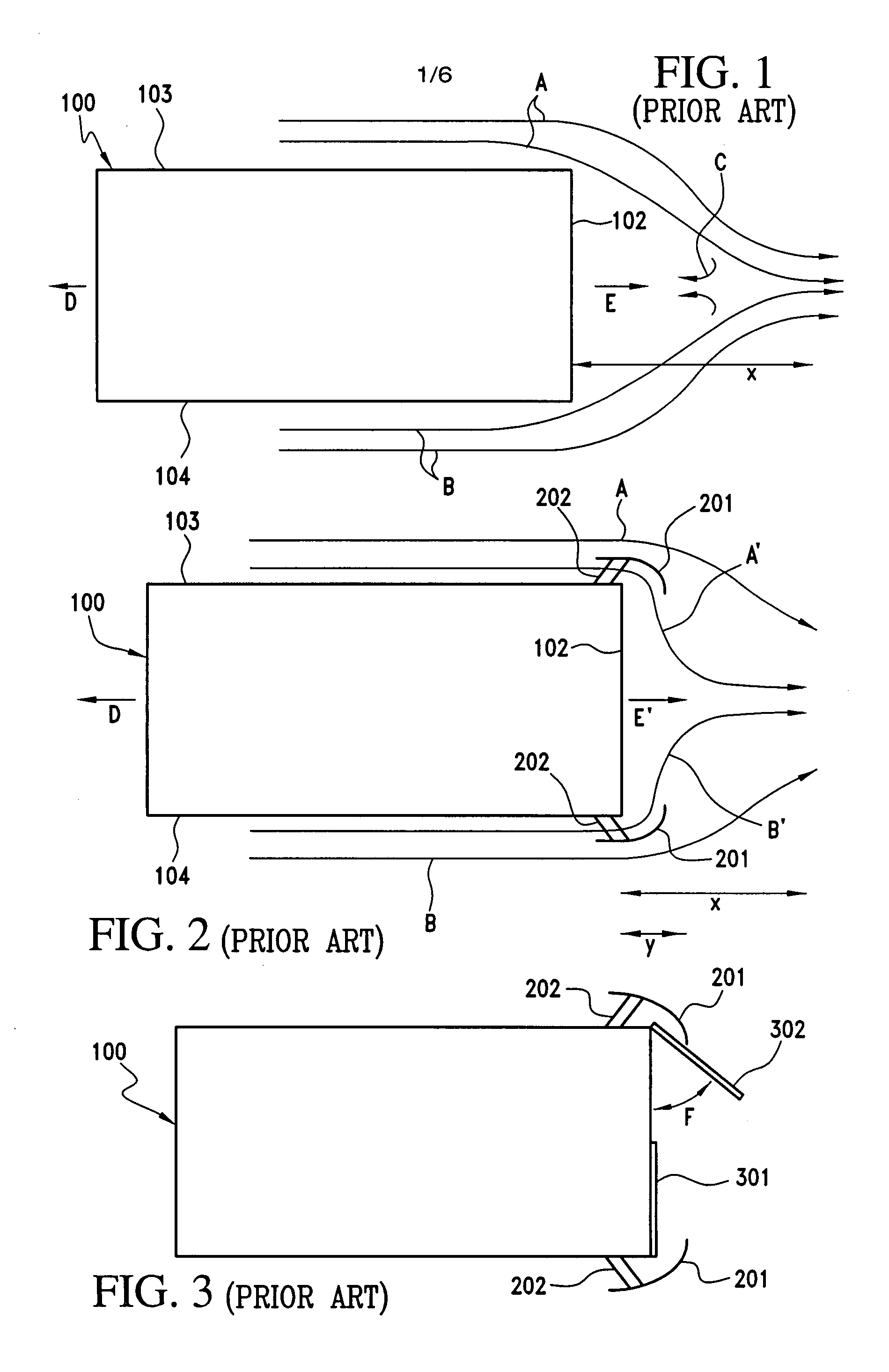
[0034]FIG. 1 shows airflow around a vehicle 100, such as a trailer or a railroad car, having a generally planar rear surface 102, a right side 103, and a left side 104, when vehicle 100 moves in a forward direction D at a desired speed. Under these conditions, air moves, relative to vehicle 100, along the sides 103 and 104 in the direction of arrows A and B, respectively. The flow of air in the direction A and the flow of air in the direction B do not reunite immediately behind rear surface 102; rather, airflows A and B reunite at a point at a certain distance X behind surface 102. A zone of low pressure air is thereby created behind rear surface 102, between the flow of air in the direction A and the flow of air in the direction B. This low pressure zone acts as a partial vacuum, and sucks air from air flows A and B in the direction of arrows C, into the zone of low pressure air. Airflow in the direction of arrows C somewhat increases the air pressure behind surface 102, but also i...


PUM


Abstract

The present invention relates to an apparatus with flexible attachments for reducing drag on a vehicle having a generally planar rear surface. The use of flexible vane attachments allows the rear doors of the trailer to fully open and close effortlessly. The apparatus includes a pair of vanes, each vane having a leading edge and a trailing edge. A first flexible attachment member connects an upper end of each vane's leading edge to a side of said vehicle, while a second flexible attachment member connects a lower end of each leading edge to the vehicle side. At least one third flexible attachment member connects the trailing edge of each vane to the rear surface of the vehicle. Other additional cables may be needed for additional vane support depending on vane length and profile. The vanes redirect air flowing along the sides of the vehicle into a volume of low pressure air behind said rear surface.

Description

BACKGROUND OF THE INVENTION[0001]1. Field of the Invention[0002]The invention relates generally to devices for reducing air flow resistance and drag on trucks, semitrailers, railway cars, and other vehicles. More particularly, the invention relates to devices for redirecting air from airstreams passing around a vehicle into low-pressure zones at the rear of the vehicle.[0003]2. Description of the Prior Art[0004]The profitability of long-distance highway cargo transport depends heavily on the cost of fuel, and on the efficiency with which the fuel is utilized. The cost of fuel is largely outside the control of the cargo transporter; however, the efficiency of fuel utilization may be increased. One method involves reducing resistance to forward motion of a vehicle through the air. Resistance to vehicular motion takes two major forms. First, the volume of air immediately in front of the vehicle acts as a barrier. A vehicle is then required to expend energy to push this volume of air as...

Claims


Application Information

Patent Timeline
Patent Type & Authority Patents(United States)
IPC IPC(8): B62D35/00B61D17/00
CPCB62D35/001Y10S180/903
Inventor SKOPIC, JOSEPH
Owner SKOPIC JOSEPH
Why Eureka
Try Eureka