
Super-resolution based on frequency domain interferometric processing of sparse multi-sensor measurements

a multi-sensor and sparse technology, applied in the direction of reradiation, measurement devices, instruments, etc., can solve the problems of inability to achieve the full resolution benefit implied by the frequency separation of sensors, the resolution achieved by the burg algorithm is limited to a factor of 2 or 3, and the number of frequency-shifted pairs required to achieve the effect of reducing the bandwidth requirements for each band and reducing the number of frequency-shifted pairs

Active Publication Date: 2007-07-10
PARSONS GOVERNMENT SERVICES
View PDF2 Cites 13 Cited by
  • Summary
  • Abstract
  • Description
  • Claims
  • Application Information

AI Technical Summary

Benefits of technology

"The present invention provides a process for obtaining super-resolution from sparse multi-sensor measurements by applying the principles of interferometry to the frequency domain. This process involves comparing the phase of signals received by the sensors operating in separate frequency bands to obtain range estimates. Ambiguities in the range estimates are removed by phase comparisons made within each band. The process can extend to a system having more than two sensors to achieve super-resolved range-doppler images. The technical effects of this invention include improved accuracy and resolution in sensor measurements and reduced bandwidth requirements for each band."

Problems solved by technology

However, the resolution achieved by the Burg Algorithm is limited to a factor of 2 or 3 (see P. R. Wu, “A Criterion for Radar Resolution Enhancement with Burg Algorithm”, IEEE Trans., Aerospace and Electronic Systems, Vol. 31, No. 3, July, 1995), the disclosure of which is expressly incorporated herein by reference.
However, none of these prior art techniques has taken advantage of the interferometer principle; and therefore, full-resolution benefit implied by the frequency separation of the sensors has not been achieved.

Method used


Image

  • Super-resolution based on frequency domain interferometric processing of sparse multi-sensor measurements
  • Super-resolution based on frequency domain interferometric processing of sparse multi-sensor measurements
  • Super-resolution based on frequency domain interferometric processing of sparse multi-sensor measurements

Examples


Embodiment Construction

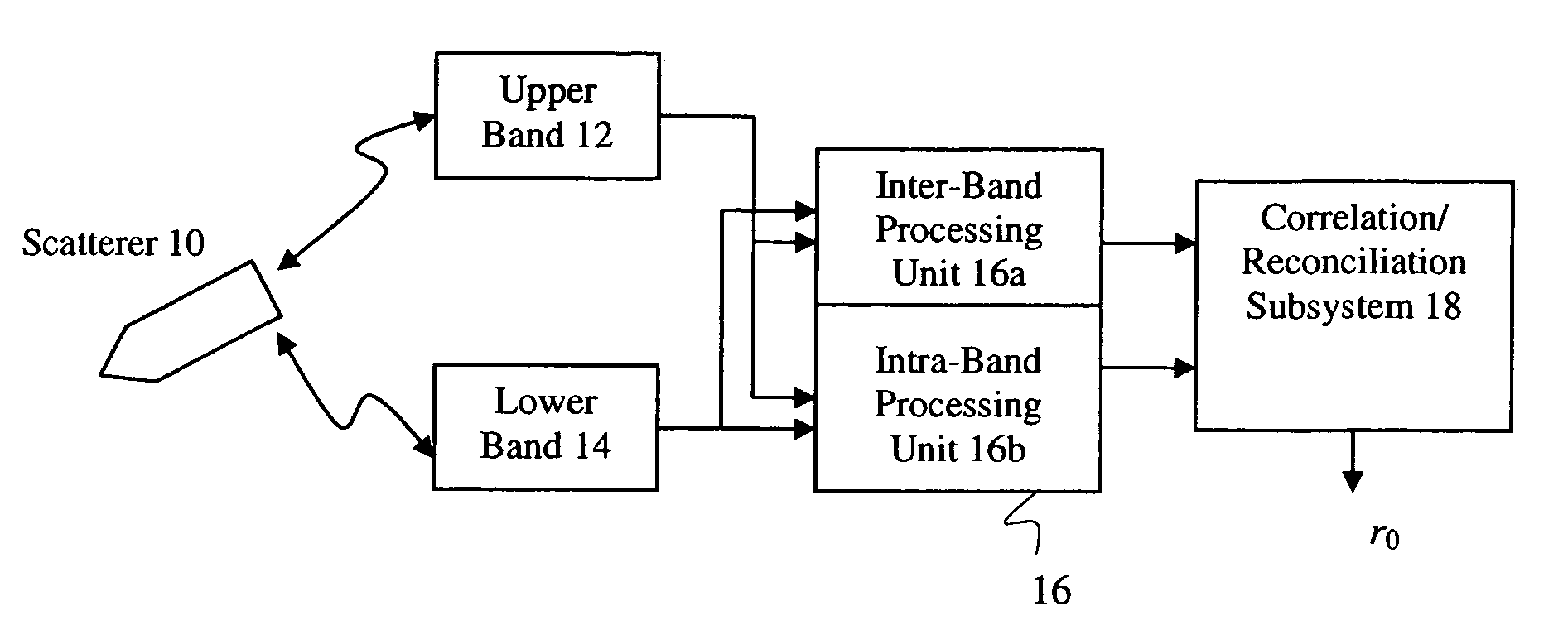
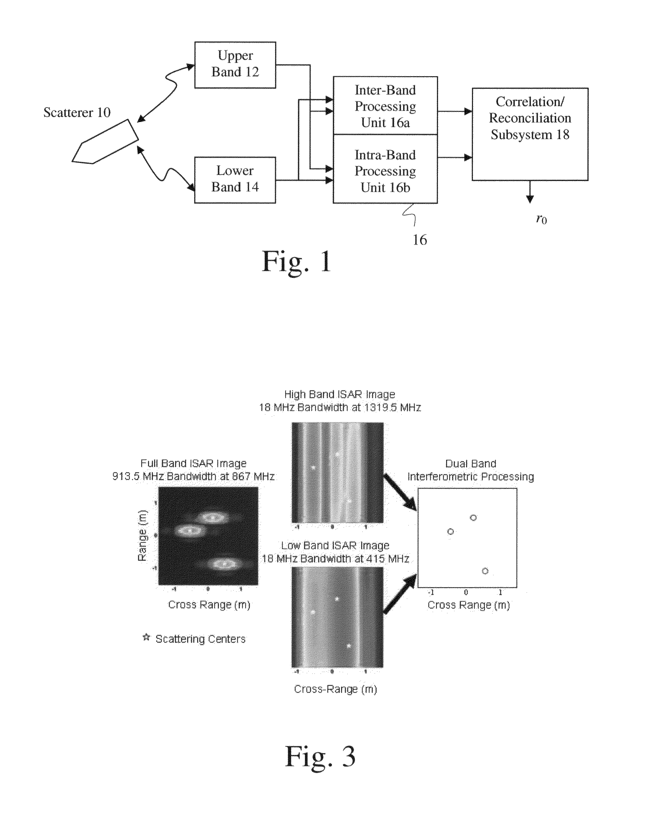
[0014]As shown in FIG. 1, the theoretical basis for frequency-domain interferometry can be illustrated by a system using a single scattering center illuminated by radar or sonar sensors operating in two frequency bands, namely, an upper band and a lower band separated from each other by ΔF Hz. As shown, the system has two sensors (transceivers) 12 and 14 operative to generate and transmit acoustic, optical or electromagnetic illumination and to receive reflected signals of the illumination from the scattering center 10. The bandwidth of the upper and lower bands is denoted as B. As the resolution obtained from the system is proportional to the frequency separation ΔF between the upper and lower bands, the frequency separation ΔF is preferably no less than ten times the bandwidth B. That is, the bandwidth B is no more than 10% of the frequency separation ΔF.

[0015]The location of the scattering center 10 is referred as a range r0 with respect to a phase reference origin. When illumina...


PUM


Abstract

A system for obtaining frequency domain interferometric super-resolution of a target scatterer, having a first and a second coherent transceivers, a mutual coherent sub-system and an estimation system. The first and second coherent transceivers are operative to produce a plurality of first and second sampling signals separated from each other by a predetermined frequency difference within the first and second sub-band, respectively. The mutual coherent sub-system is coupled to the first and second coherent transceivers to receive phase and amplitude of the first and second sampling signals, so as to evaluate an ambiguous range estimate from a pair of the first and second sampling signals and an unambiguous range estimate from a pair of the first and / or second sampling signals. The estimation system follows the mutual coherent sub-system to reconcile the ambiguous and unambiguous range estimates so as to obtain a target signature with a super-resolution defined by a frequency offset between the first and second sub-bands.

Description

CROSS-REFERENCE TO RELATED APPLICATIONS[0001]This application claims the benefit of U.S. Provisional Application No. 60 / 599,608 entitled “SUPER-RESOLUTION BASED ON FREQUENCY DOMAIN INTERFEROMETRIC PROCESSING OF SPARSE MULTI-SENSOR MEASUREMENTS” filed Aug. 6, 2004, the entirety of the disclosure of which is expressly incorporated herein by reference.STATEMENT RE: FEDERALLY SPONSORED RESEARCH / DEVELOPMENT[0002]This application is a subject invention under Contract / Grant No. HQ0006-03-C-0049 with the United States Government, and as such the United States Government has rights therein.BACKGROUND OF THE INVENTION[0003]The present invention relates in general to a method of obtaining super-resolution in range for sensor systems such as electromagnetic, acoustic, electro-optics and other spectral regimes particularly where the individual sensors are limited in bandwidth. More particularly, the present invention relates to a method for producing two-dimensional (range-Doppler) images with s...

Claims


Application Information

Patent Timeline
Patent Type & Authority Patents(United States)
IPC IPC(8): G01S13/90
CPCG01S13/88G01S13/89G01S15/87G01S17/87
Inventor WU, PEI-RINBURROWS, MICHAEL T.DRYDEN, GORDON L.
Owner PARSONS GOVERNMENT SERVICES
Learn More