Electric switch

a technology of electric switch and switch body, which is applied in the direction of mechanical control devices, manual control with single control member, sports apparatus, etc., can solve the problems of inability to determine whether the switch is suitable for use, and no information as to how the functionality of rotation and movement can be provided, and achieves high degree of functionality, small physical size, and high reliability of operation.

Active Publication Date: 2007-07-10
MARQUARDT GMBH SCHLOSSTRASSE 16 7201 RIETHEIM-WEILHEIM 1 WEST GERMANY
View PDF26 Cites 19 Cited by
  • Summary
  • Abstract
  • Description
  • Claims
  • Application Information

AI Technical Summary

Benefits of technology

[0009]In a first embodiment of the electrical switch according to the invention, the operating element interacts with rotation means in such a way that the operating element can be rotated and in the process has a switching effect on a switching element. A controllable external rotor electric motor is operatively connected to the operating element, with at least a part of the rotation means comprising the external rotor of the external rotor motor. The external rotor motor allows a variable tactile sense to be produced for the rotary movement of the operating element.
[0031]high moment of inertia thus minimizing oscillations in the rest position,

Problems solved by technology

In particular, it contains no information as to how the functionality of rotation and movement can be provided by means of a single operating element.
Finally, it is also not possible to determine whether this switch is suitable for use in a motor vehicle where the installation areas are confined.

Method used


Image

  • Electric switch
  • Electric switch
  • Electric switch

Examples


Embodiment Construction

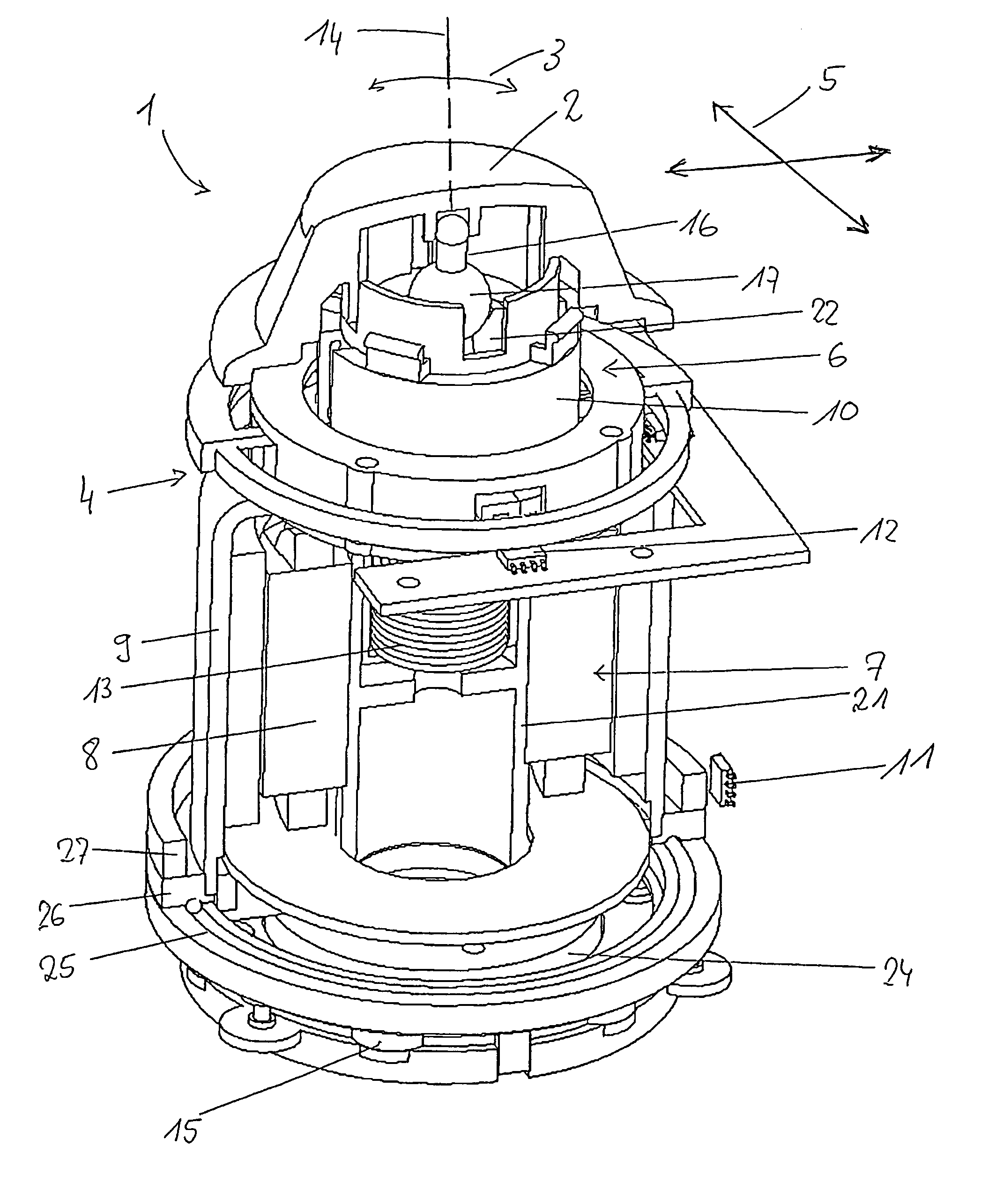
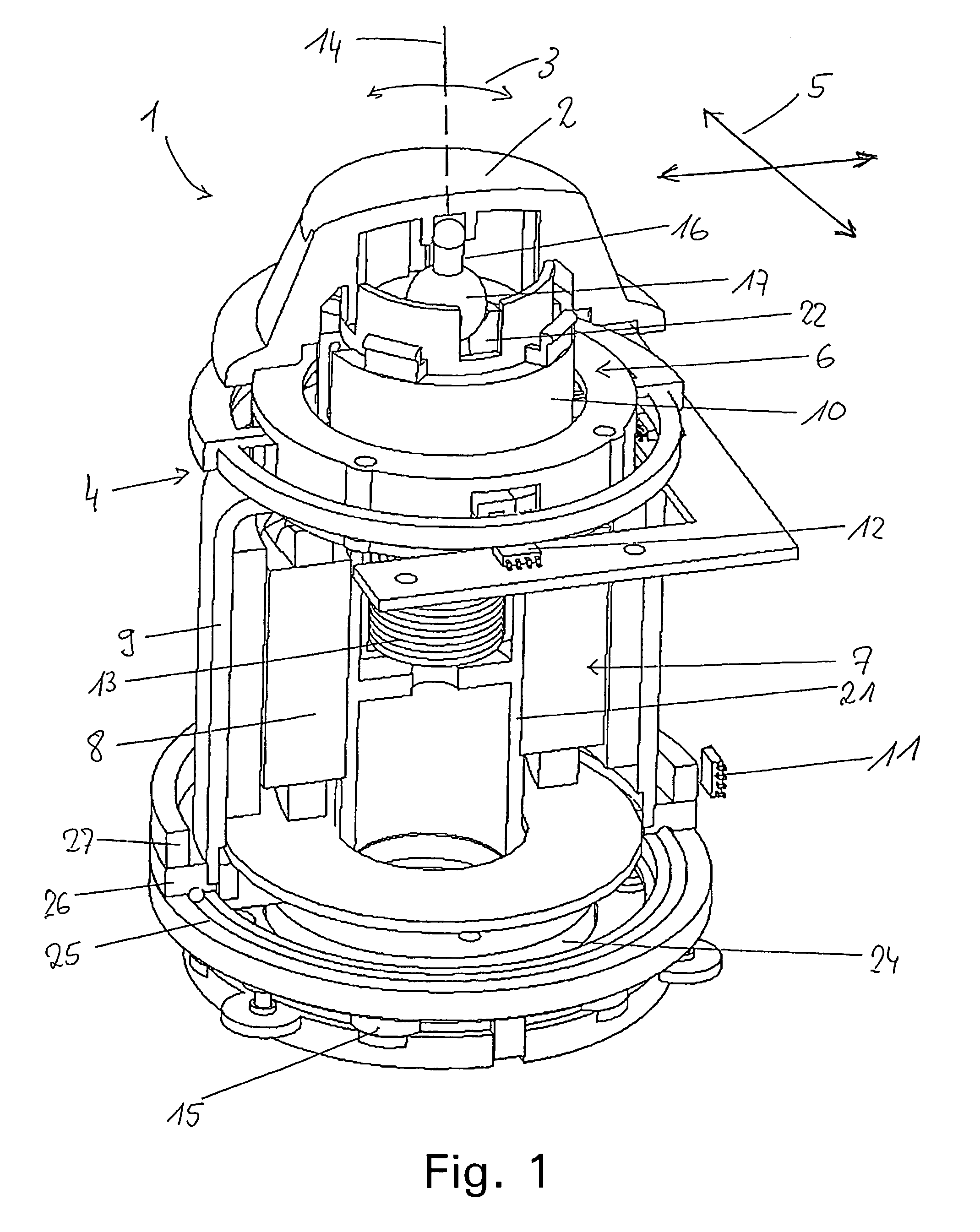
[0046]FIG. 1 shows an electrical switch 1 which is in the form of a joystick or cursor switch. The switch 1 has an operating element 2 which can be rotated by a user manually in two opposite rotation directions 3. For this purpose, the operating element 2 interacts with rotation means 4. The operating element 2 has a switching effect on a switching element 11 during rotation. A controllable external rotor electric motor 7 is operatively connected to the operating element 2 in such a way that a tactile sense is produced for the rotary movement of the operating element 2. The tactile sense can be varied depending on the drive level of the external rotor motor 7. By way of example, the rotation of the operating element 2 may be made harder or easier, may be in the form of latching steps, or the like, depending on the situation.

[0047]The external rotor motor 7 has an inner stationary stator 8 as well as an outer rotating external rotor 9. The stator 8 of the external rotor motor 7 is ar...


PUM


Abstract

An electrical switch having a form of one of a joystick and a cursor switch is provided, including an operating element. The operating element interacts with at least one of rotation means such that the operating element can be rotated, and with movement means such that the operating element can be moved in at least one linear direction on a movement plane. The operating element has a switching effect on a switching element during rotation and / or during movement.

Description

CROSS REFERENCE TO RELATED APPLICATIONS[0001]This application is a continuation of International Application No. PCT / EP2004 / 008835 having an international filing date of Aug. 6, 2004, which designated the United States, and claims the benefit under 35 USC §119(a)–(d) of German Application No. 103 36 507.9 filed Aug. 8, 2003, the entireties of which are incorporated herein by reference.FIELD OF THE INVENTION[0002]The present invention relates to an electrical switch.BACKGROUND OF THE INVENTION[0003]Electrical switches which are in the form of a joystick switch or cursor switch are used by a user to enter data for an electrical appliance. By way of example, switches such as these are used for car radios, navigation appliances, on-board computers or else for controlling other functions in motor vehicles, in which case, by way of example, the switch may be arranged on the motor vehicle steering wheel. In particular, an electrical switch such as this can also be used as a multifunction s...

Claims


Application Information

Patent Timeline
Patent Type & Authority Patents(United States)
IPC IPC(8): G09G5/08G06F3/00H01H25/00H01H25/04
CPCH01H25/002H01H25/008H01H25/04G05G9/047H01H2003/008H01H2025/004
Inventor BADER, MICHAELKRAMER, MARKUS
Owner MARQUARDT GMBH SCHLOSSTRASSE 16 7201 RIETHEIM-WEILHEIM 1 WEST GERMANY
Why Eureka
Try Eureka