Eureka AIR delivers breakthrough ideas for toughest innovation challenges, trusted by R&D personnel around the world.

Binocular magnifying glasses

a technology binocular lenses, which is applied in the field can solve the problems of wearer being required to lean his or her head, wearer being unable to withstand long-term use of binocular magnifying glasses, and additional problems, so as to reduce the burden on the wearer

Active Publication Date: 2007-07-10
ASAHI KOGAKU KOGYO KK
View PDF8 Cites 11 Cited by
  • Summary
  • Abstract
  • Description
  • Claims
  • Application Information

AI Technical Summary

Benefits of technology

[0005]The present invention is advantageous in that it provides binocular magnifying glasses which are capable of matching a right image to a left image when an adjustment of convergence is accomplished while reducing a burden on a wearer by deflecting an optical path in each of optical systems for right and left eyes.
[0007]With this configuration, it becomes possible to perform an adjustment of convergence keeping a condition in which an inclination of an image is corrected. Therefore, a right image and a left image can be matched to each other when the adjustment of convergence is accomplished while reducing a burden on a wearer by deflecting an optical path in each of optical systems for right and left eyes.
[0012]With this configuration, it becomes possible to perform an adjustment of convergence keeping a condition in which an inclination of an image is corrected. Therefore, a right image and a left image can be matched to each other when the adjustment of convergence is accomplished while reducing a burden on a wearer by deflecting an optical path in each of optical systems for right and left eyes.
[0018]With this configuration, it is possible to match optical axes to visual axes using the β-rotation and to adjust convergence using the γ-rotation. Further, inclination of the image cased by the β-rotation and the γ-rotation can be corrected by the adjustment of the angle ψ. Therefore, it becomes possible to adjust convergence keeping a condition in which inclination of the image is not caused while deterioration of the image is prevented.
[0026]With this configuration, it is possible to match optical axes to visual axes using the β-rotation and to adjust convergence using the γ-rotation. Further, inclination of the image cased by the β-rotation and the γ-rotation can be corrected by the adjustment of the angle ψ. Therefore, it becomes possible to adjust convergence keeping a condition in which inclination of the image is not caused while deterioration of the image is prevented.
[0033]With this configuration, the prism can attain the function of deflecting the optical axis in each magnifying glass, rotating the image by 180°, and correcting the inclination of the image during the adjustment of convergence.

Problems solved by technology

However, there is a problem that the wearer is required to lean his or her head by an angle raging from 30° to 60° with respect to a horizontal direction because an optical path of each of the magnifying optical systems for the right and left eyes is a straight line.
Therefore, the wearer is not able to withstand long-term use of the binocular magnifying glasses.
When the optical path in each of the magnifying optical systems for the right and left eyes is bent by an angle range of 30° through 60° so as to reduce the burden on the wearer, an additional problem occurs.

Method used


Image

  • Binocular magnifying glasses
  • Binocular magnifying glasses
  • Binocular magnifying glasses

Examples


first embodiment

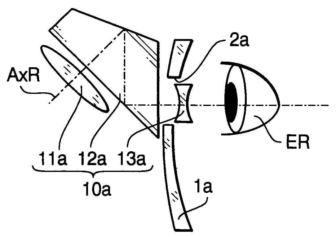
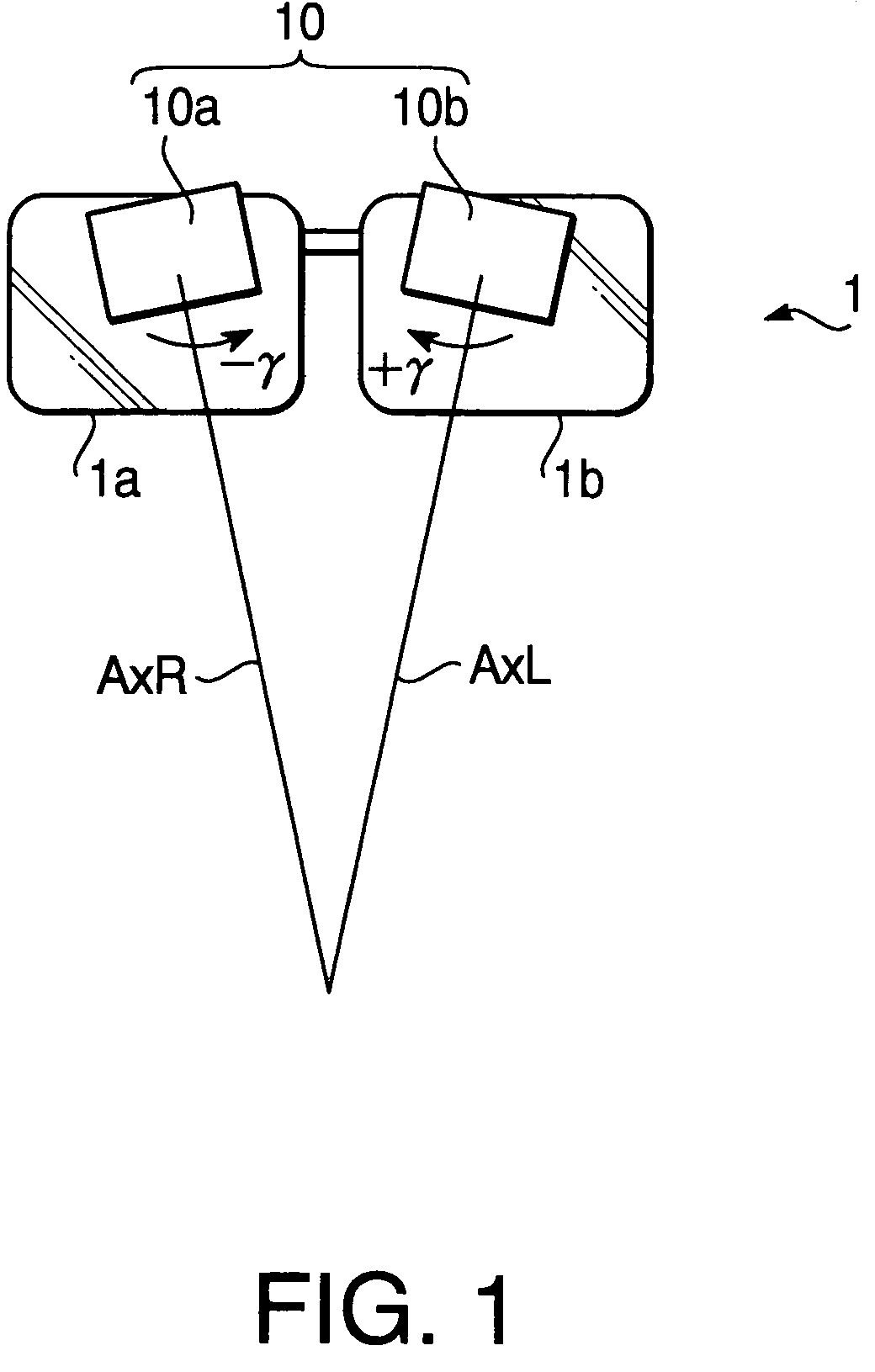
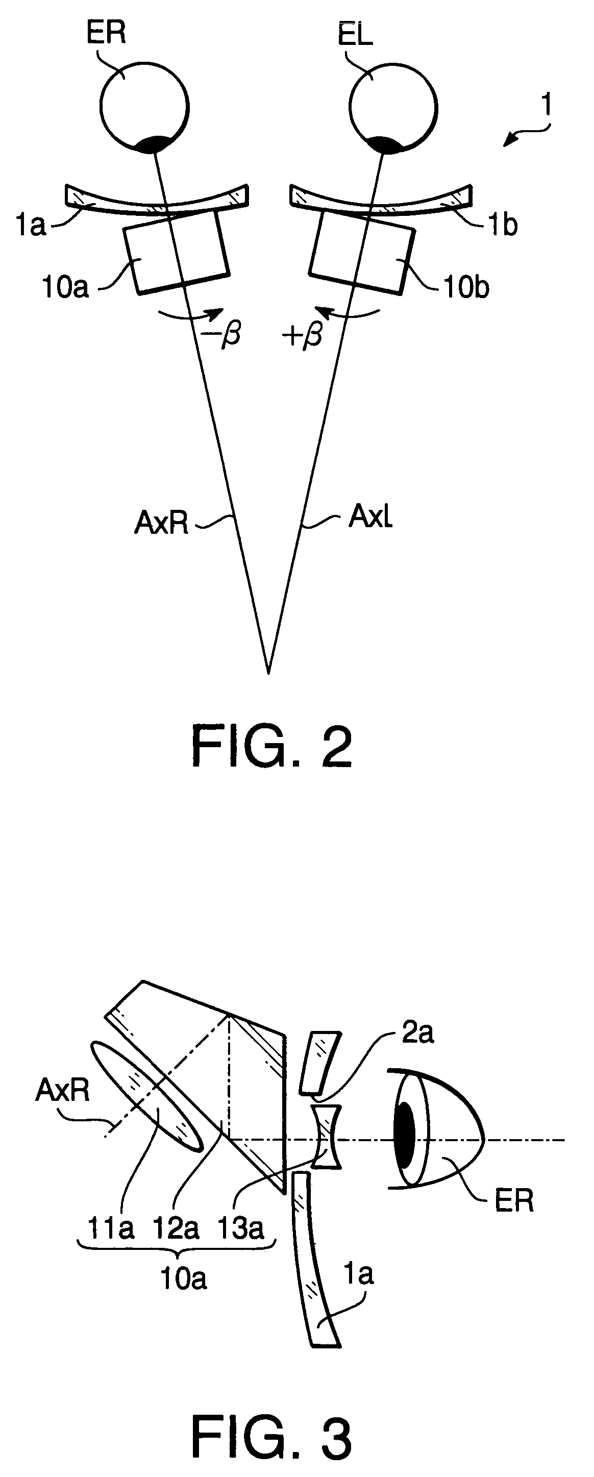
[0057]FIGS. 1–3 show a configuration of binocular magnifying glasses 10 to which an adjustment method according to a first embodiment of the invention is applied. FIG. 1 is a front view of the binocular magnifying glasses 10. FIG. 2 is a top view of the binocular magnifying glasses 10. FIG. 3 is a side view of the binocular magnifying glasses 10 showing a configuration of a magnifying glass 10a for the right eye (ER).

[0058]As shown in FIGS. 1 and 2, the binocular magnifying glasses 10 have the magnifying glass 10a for the right eye (ER) attached to a lens 1a of eyeglasses 1, and a magnifying glass 10b for the left eye (EL) attached to a lens 1b of the eyeglasses 1. An axis AxR is an optical axis of the magnifying glass 10a for the right eye and an axis AxL is an optical axis of the magnifying glass 10b for the left eye.

[0059]As shown in FIG. 3, each of the magnifying glasses 10a and 10b has a magnifying optical system to examine an object in a magnified manner, and a deflector which...

second embodiment

[0102]Hereafter, a second embodiment according to the invention will be described.

[0103]FIGS. 12–14 show a configuration of binocular magnifying glasses 20 according to the second embodiment of the invention. FIG. 12 is a front view of the binocular magnifying glasses 20. FIG. 13 is a top view of the binocular magnifying glasses 20. FIG. 14 is a side view of the binocular magnifying glasses 20 showing a configuration of a magnifying glass 20a for the right eye (ER).

[0104]As show in FIGS. 12 and 13, the binocular magnifying glasses 20 have the magnifying glass 20a for the right eye (ER) attached to a lens 5a of eyeglasses 5, and a magnifying glass 20b for the left eye (EL) attached to a lens 5b of the eyeglasses 5. An axis AxR is an optical axis of the magnifying glass 20a for the right eye and an axis AxL is an optical axis of the magnifying glass 20b for the left eye.

[0105]Since the configuration of the binocular magnifying glasses 20 is similar to the configuration of binocular ma...

third embodiment

[0147]FIG. 21 shows a configuration of a magnifying glass 50c according to a third embodiment of the invention. Similarly to the magnifying glass 20a (20b) of the second embodiment, the magnifying glass 50c can be attached to the eyeglass 5. That is, the magnifying glass 50c has substantially the same configuration as the magnifying glass 20a (20b) except for a mirror group 52c.

[0148]The definitions of adjustment axes defined with reference to FIG. 6 are also applied to the third embodiment.

[0149]As shown in FIG. 21, the magnifying glass 50c has a objective lens 51c having a positive power, the mirror group 52c which deflects light incident thereon from an objective side, and an eyepiece 53c having a positive power, which are arranged in that order from the object side.

[0150]Light passed through the objective lens 51 is reflected four times by the mirror group 52c, and thereafter passes through the eyepiece 53c to be incident on the right eye ER. In FIG. 21, the deflection angle θ,...


PUM


Abstract

An adjustment method includes rotating a pair of magnifying glasses in directions opposite to each other using γ-rotation, and correcting inclination of an image, caused by the γ-rotation, by rotating the pair of magnifying glasses in directions opposite to each other using the β-rotation, given that rotation about each of axes XL and XR, which respectively correspond to visual axes of left and right eyes when an object distance is infinite in a condition of a primary position, is represented by the γ-rotation, and that rotation about each of axis YL and YR, which are respectively perpendicular to the axes XL and XR and are also perpendicular to a z-axis which perpendicularly intersects with the axis XL at a position of a deflector for the left eye and the axis XR at a position of the deflector for the right eye, is represented by the β-rotation.

Description

BACKGROUND OF THE INVENTION[0001]The present invention relates to binocular magnifying glasses which are worn for examining an object in a magnified manner when performing precision work by hand, etc.[0002]In conventional binocular magnifying glasses of this type, there has been known the technology disclosed in Japanese Patent Provisional Publication No. HEI 7-199083. The binocular magnifying glasses have a pair of magnifying optical systems, each system being provided for each of the right and left eyes. Each magnifying optical system includes an objective lens having a positive power and an eyepiece having a negative power arranged in that order from an object side to an eye side. Optical centers of the objective lens and the eyepiece of each magnifying optical system are positioned outside a line connecting the center of rotation of the eye and the object point as shown in FIG. 1 of the publication.[0003]With this configuration, the binocular magnifying glasses providing a balan...

Claims


Application Information

Patent Timeline
IPC IPC(8): G02B23/00G02B21/20G02B25/00
CPCG02C7/088G02B25/004A47J27/21183A47J31/0615A47J27/21008
Inventor KANAI, MORIYASU
Owner ASAHI KOGAKU KOGYO KK
Why Eureka
Eureka Blog
Learn More