
System and method for reducing the size of RC circuits

a technology of reducing circuits and circuit topologies, applied in the field of circuit analysis, can solve problems such as inability to mathematical models that presume special, and often non-standard simulator capabilities, and achieve reduced circuit topologies that contain certain types of circuit topologies. the effect of the reduction schem

Inactive Publication Date: 2007-07-10
CADENCE DESIGN SYST INC
View PDF34 Cites 20 Cited by
  • Summary
  • Abstract
  • Description
  • Claims
  • Application Information

AI Technical Summary

Benefits of technology

[0008]The present invention includes a method of transforming a first topology to a reduced topology, said first topology representing an abstraction of one or more objects, said first topology further comprising a plurality of inter-connected elements. The method comprises the steps of: (a) identifying on...

Problems solved by technology

A disadvantage of these transformations, however, is that the reduced circuit model is not realizable.
A drawback associated with this unrealizability is that the resulting mathematical models may presume special, often non-standard simulator capabilities.
A weakness of the approach in Liao is that the reduction scheme may not be effective for circuits containing certain types of circuit topologies, such as coupling capacitors or an unbalanced tree in a memory block.
Moreover, there is no guarantee that errors resulted from the approximations are controlled to a minimized or negligible level so that certain properties of the original circuit are preserved.
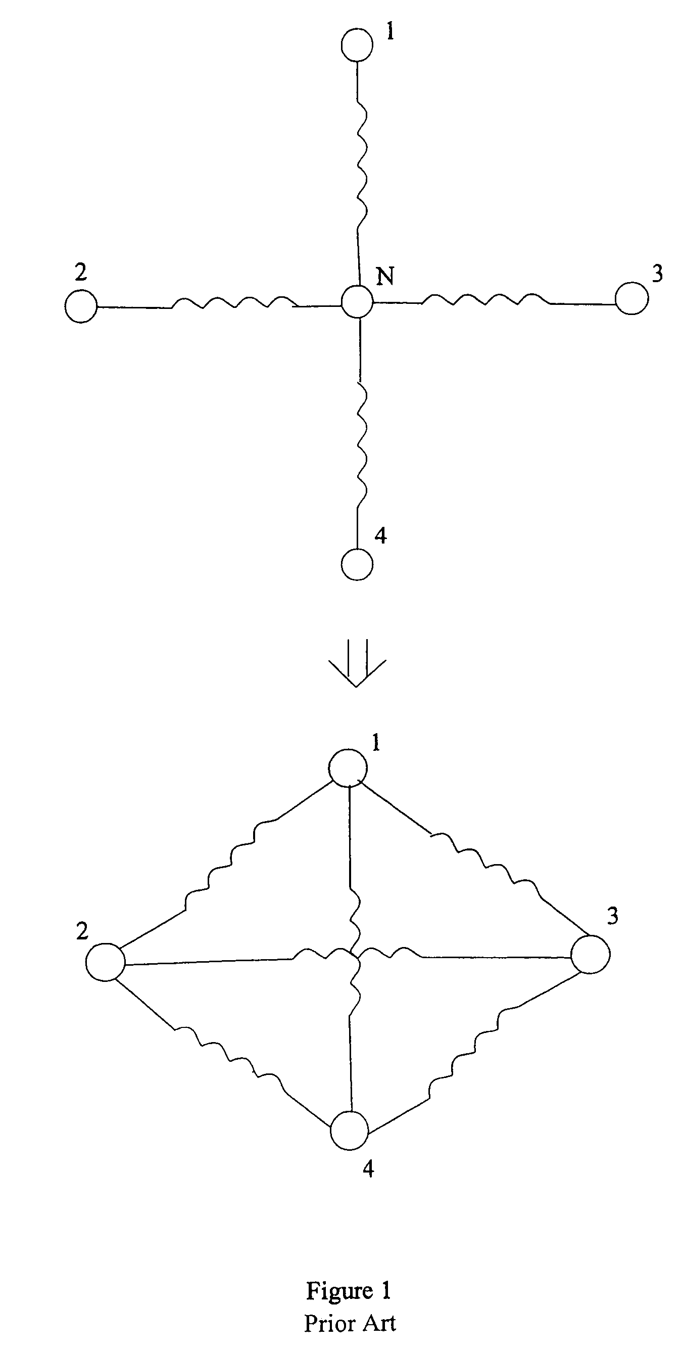
If node i and node j had been connected to node N through conductance giN and gjN, insert a conductance giNgjN / γN between nodes i and j. If node i had a capacitor CiN connected to node N and node j had a conductance gjN connected to node N, insert a capacitor CiNgjN / γN between nodes i and j. A drawback of the TICER algorithm is that it only focuses on controlling the accuracy of circuit simulation and ignores the topological impact of node eliminations.
The increased number of resistors or capacitors could further complicate the entanglement between the remaining nodes.
As a result, TICER may not achieve significant circuit reduction for large circuit networks

Method used


Image

  • System and method for reducing the size of RC circuits
  • System and method for reducing the size of RC circuits
  • System and method for reducing the size of RC circuits

Examples


Embodiment Construction

[0032]One embodiment of the present invention comprises a method of transforming a first topology to a reduced topology. The first topology may represent an abstraction of one or more objects. The one or more objects can be circuits or any other objects. The first topology may further comprise a plurality of inter-connected elements. These inter-connected elements can be circuit elements, such as nodes, capacitors, transistors, or any other elements. The reduced topology may be obtained by eliminating elements or making approximations.

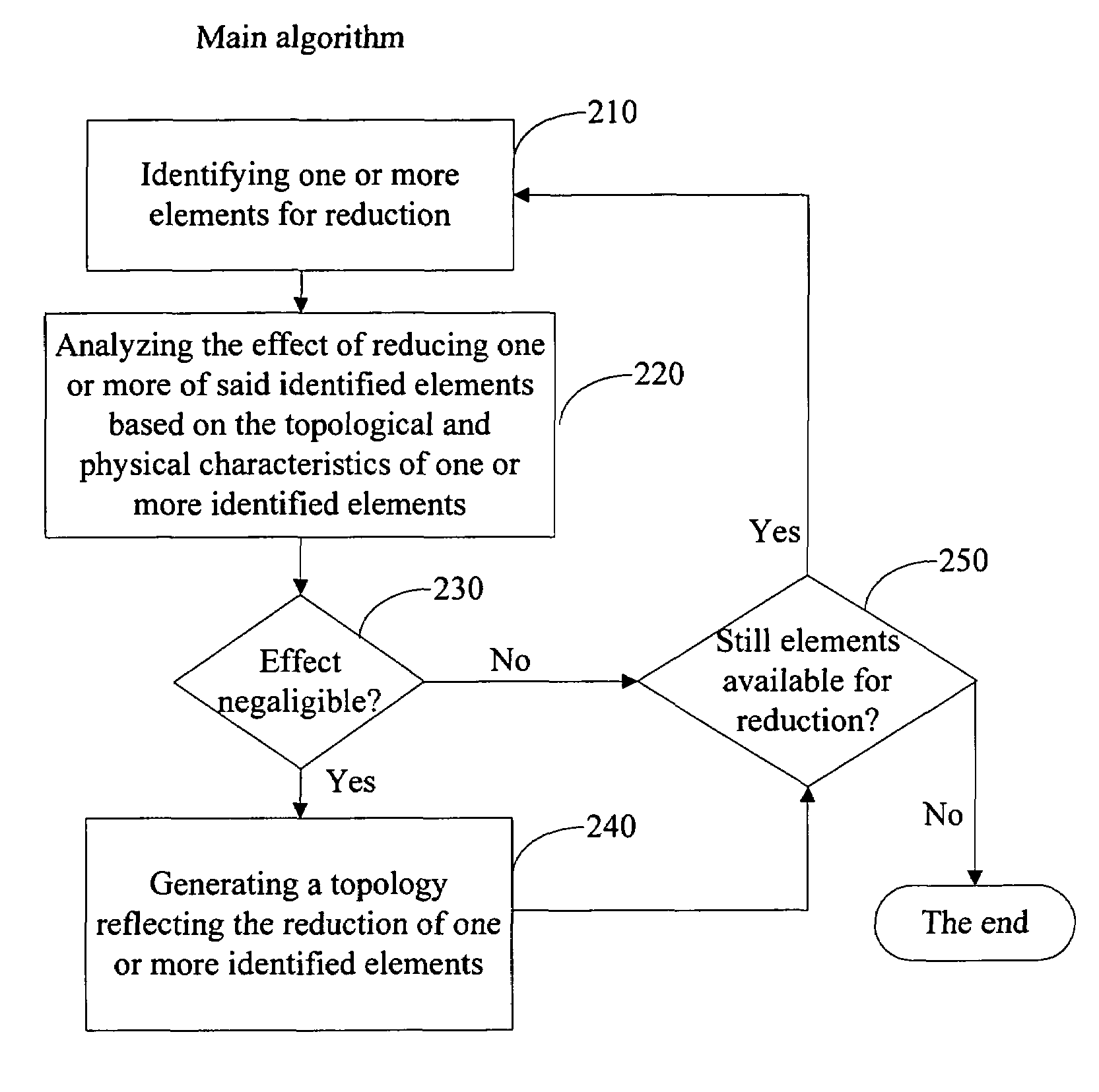
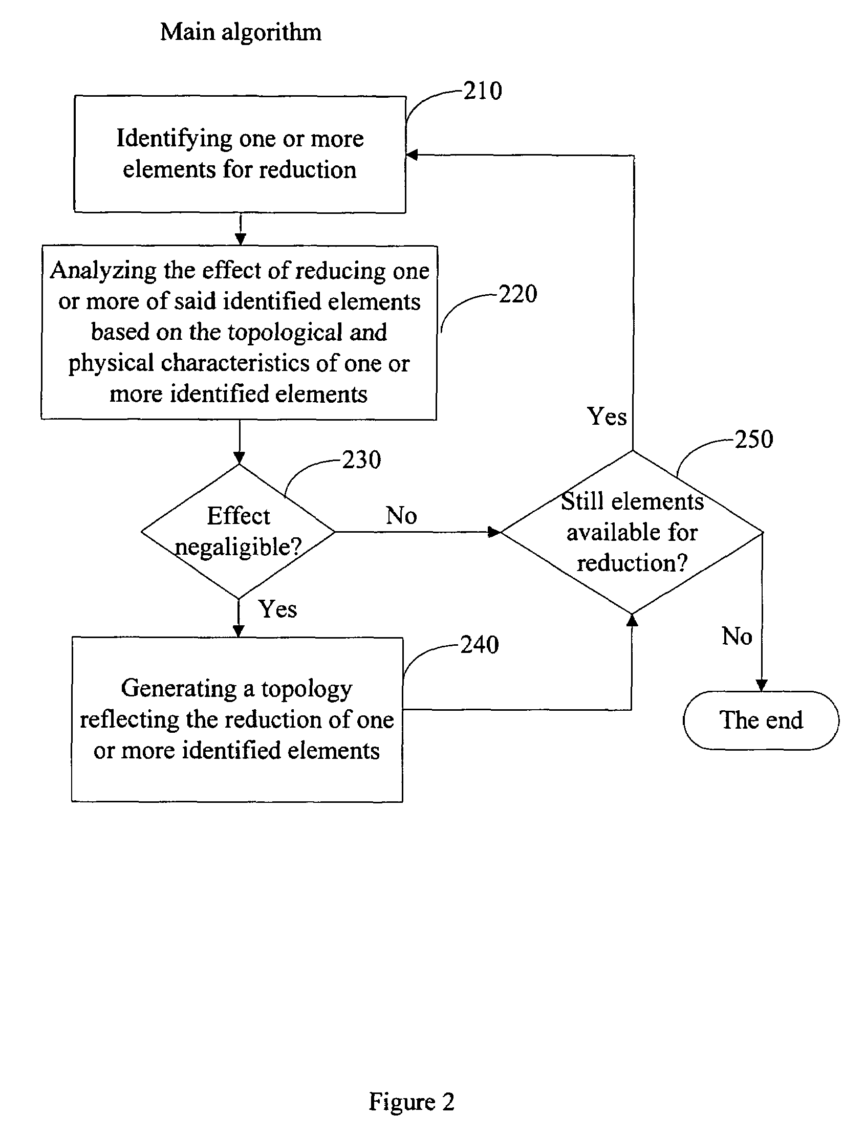
[0033]A flow chart of one method of the present invention is shown in FIG. 2. Step 210 of the method identifies one or more elements for reduction. The one or more elements for reduction can be identified according to any applicable topological or physical standard. In one embodiment, symmetric nodes on the topology may be identified since these nodes may represent points or parts of the objects having similar behavior. Approximations of the first topo...


PUM


Abstract

A method of transforming a first topology to a reduced topology is disclosed. One preferred embodiment of the present invention includes a method of transforming a circuit from a first topology to a reduced topology, said first topology comprising a plurality of inter-connected circuit elements. The method comprises the steps of: (a) identifying one or more circuit elements; (b) analyzing the effect of reducing one or more of said identified circuit elements on the topological and physical characteristics of said circuit; and (c) if the effect satisfies a first standard, generating a second topology reflecting the reduction of one or more identified circuit elements.

Description

FIELD OF INVENTION[0001]This invention relates in general to circuit analysis and in particular to a system and method for transforming a circuit from its original topology to a reduced topology.BACKGROUND OF INVENTION[0002]Modern circuit simulations or verifications often encounter circuit models having a large number of inter-connected circuit elements. For example, during the final timing verification of Integrated circuits (IC), the number of parasitic resistors and capacitors in the circuit model may reach or exceed 107. In order to improve the efficiency of circuit analysis, a variety of RC reduction technologies have been developed during the last decade.[0003]The dominant trend in RC reduction has been towards transforming the original RC circuit network into a mathematical macro-model so that certain mathematical techniques can be utilized to generate a reduced mathematical circuit model. (See Rohrer et. al., “Asymptotic Waveform Evaluation for Timing Analysis”, IEEE Trans....

Claims


Application Information

Patent Timeline
IPC IPC(8): G06F17/50
CPCG06F17/5036G06F30/367
Inventor QIN, WANGGUOMCGAUGHY, BRUCE W.KONG, JUNYU, QINGJIAN
Owner CADENCE DESIGN SYST INC
Learn More