
Fixing tool for quickly setting up a secure device

a technology for fixing tools and secure devices, applied in the direction of lighting and heating apparatus, instruments, and the details of semiconductor/solid-state devices, can solve the problems of consuming much more power, c-type retaining rings become tedious, and each electronic device can perform huge and complicated functions, so as to achieve less time for setting up the secure device, the effect of avoiding possible injuries and increasing production capacity

Inactive Publication Date: 2007-07-17
ASIA VITAL COMPONENTS SHENZHEN CO LTD
View PDF8 Cites 0 Cited by
  • Summary
  • Abstract
  • Description
  • Claims
  • Application Information

AI Technical Summary

Benefits of technology

The present invention provides a fixing tool for quickly setting up a secure device. The tool includes a main member, a driving element, and an ejection member. The ejection member can move between a prior-ejecting position and an ejection position. When the ejection member is located at the prior-ejecting position, it pushes the engaging member to engage with the secure unit, which is attached to the electronic component, so as to mount the secure device to the electronic component. The fixing tool allows for quick and safe mounting of secure devices, reducing injury risks and improving production efficiency. It also simplifies the process of setting up the secure device and reduces inconvenience.

Problems solved by technology

Relatively, each electronic device can perform huge and more complicated functions and it consumes much more power so that more heat is generated and a heat dissipation device such as a radiator has to be mounted to the electronic device for removing the heat in order to keep operation of the whole electronic system normally
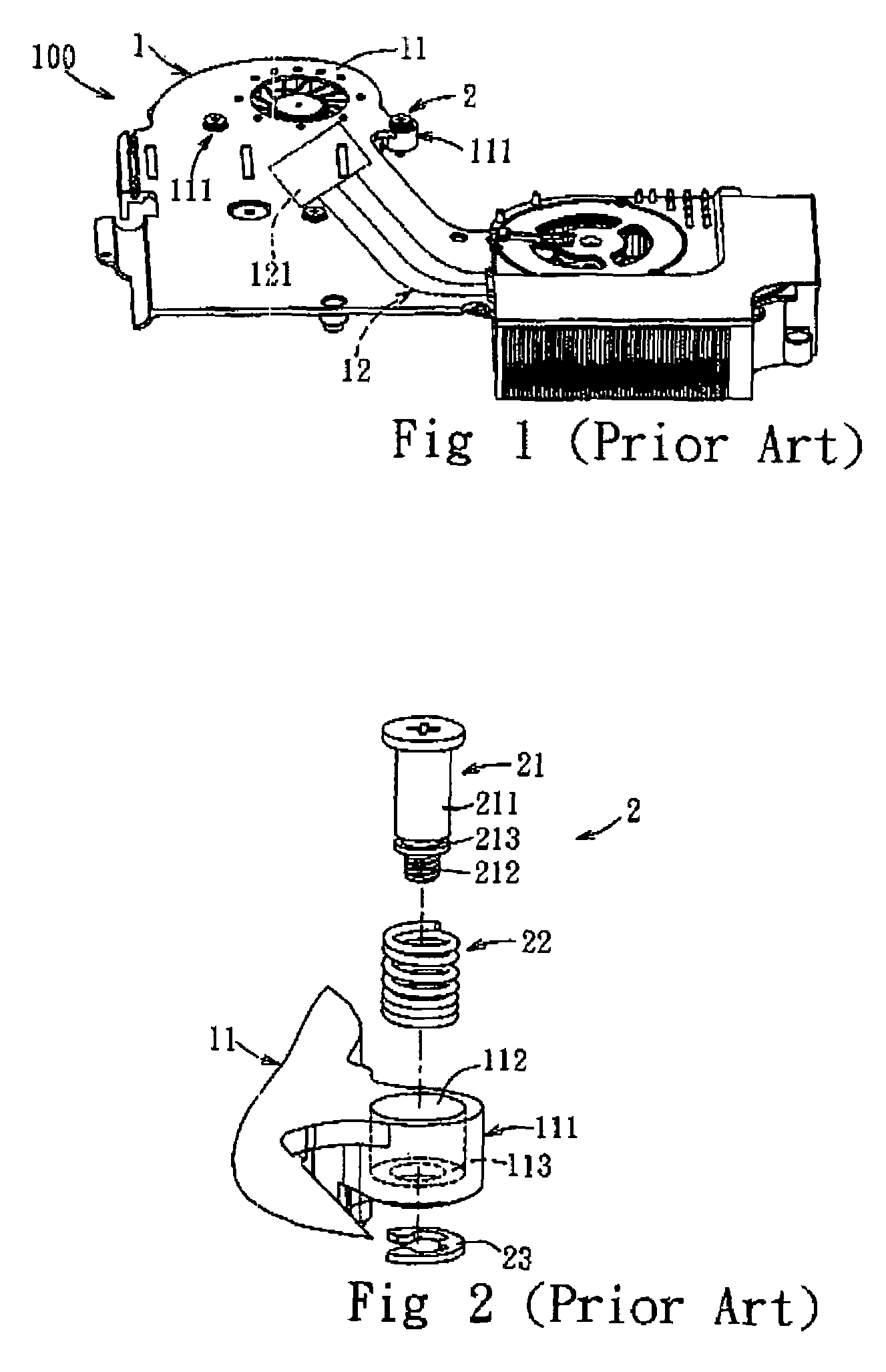
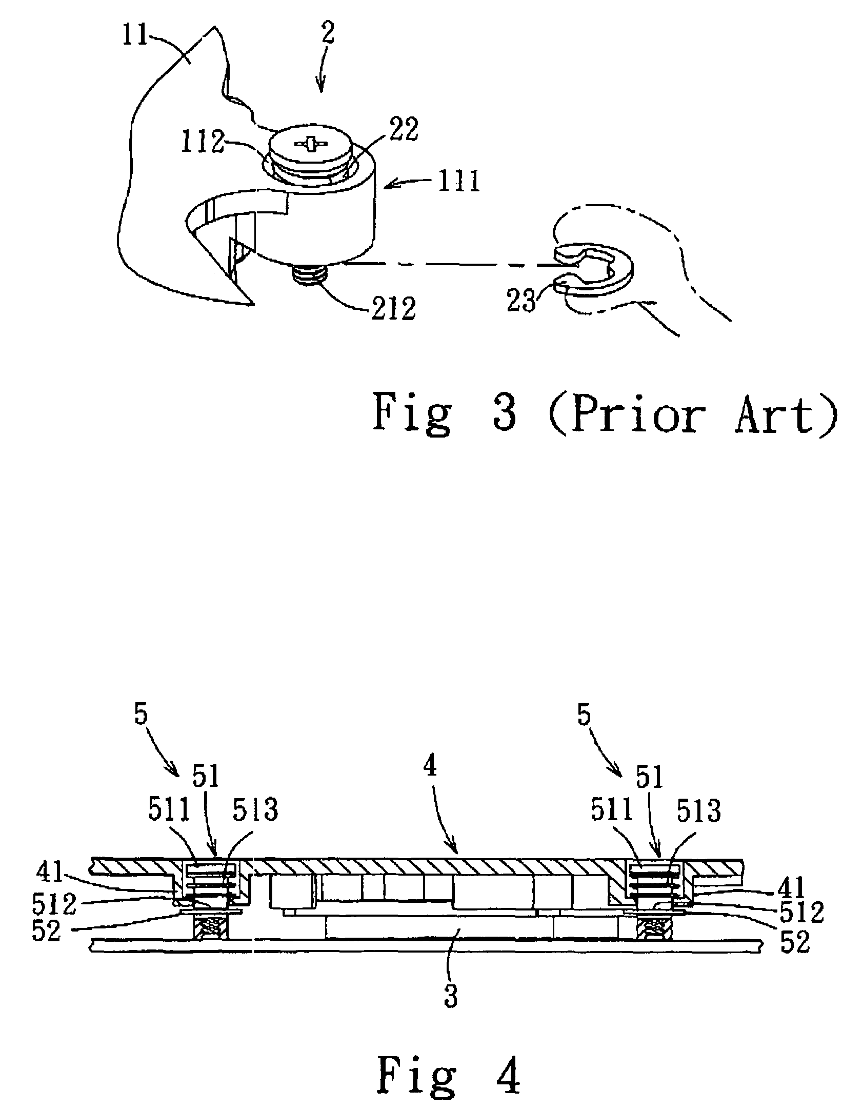
The C-type retaining ring 23 in the preceding conventional device is engaged to the annular recess 213 manually but it is very inconvenient that the small and flat retaining ring 23 has to be picked up carefully before engaging with the annular recess 213.
On the other hand, it is easy for a group of C-type retaining rings to attract each other due to static electric charges such that picking up one of the C-type retaining rings becomes very tedious.
In addition, the force being exerted excessively with an unevenly positioned C-type retaining ring may result in injury of hand once the hand hits the electronic component.
In this way, worse production efficiency is obtained with increased production cost.

Method used


Image

  • Fixing tool for quickly setting up a secure device
  • Fixing tool for quickly setting up a secure device
  • Fixing tool for quickly setting up a secure device

Examples


Embodiment Construction

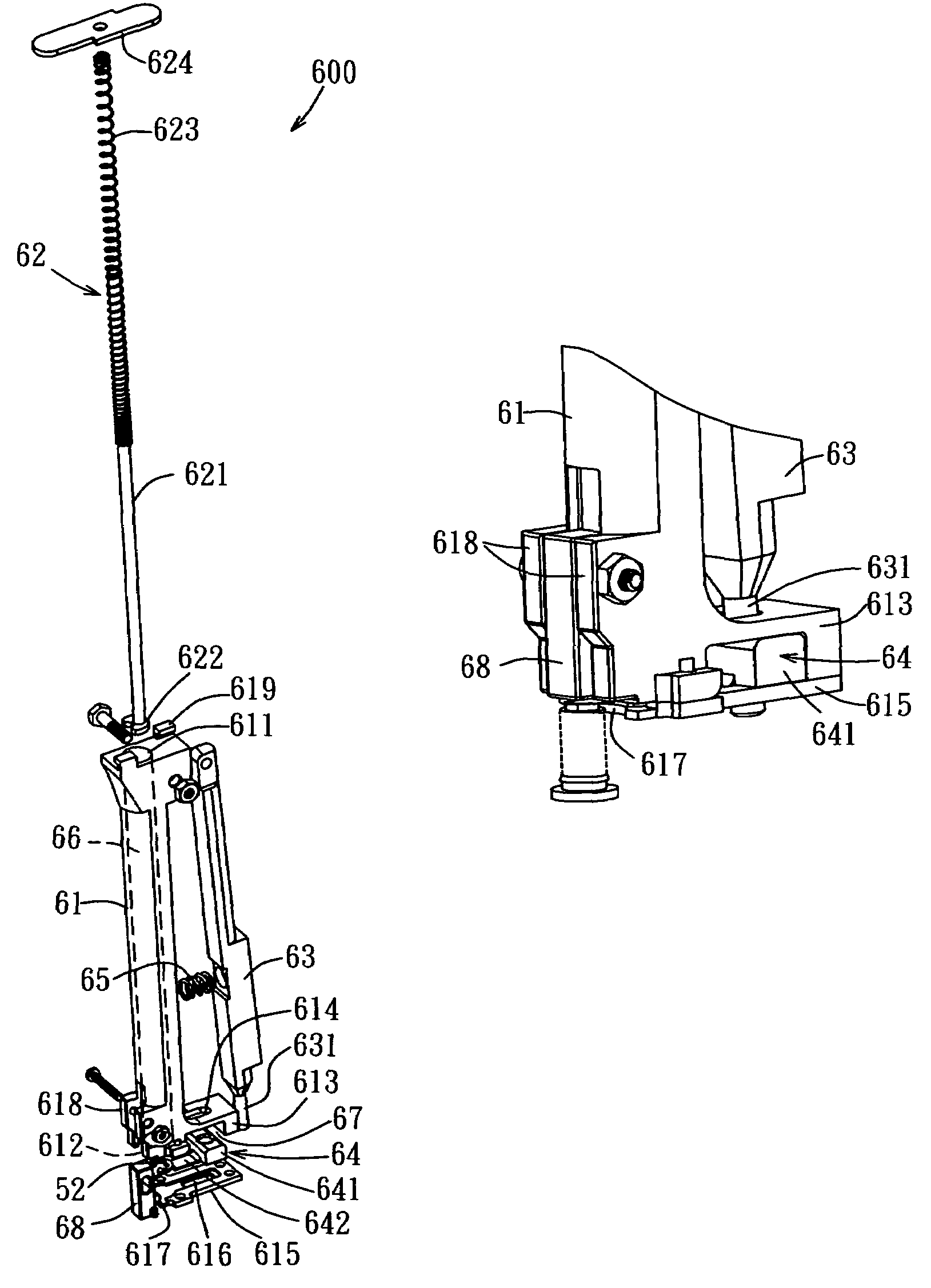
[0022]Referring to FIGS. 4, 5 and 6, a preferred embodiment of a fixing tool for quickly setting up a secure device according to the present invention is illustrated. The fixing tool 600 of the preferred embodiment is used for setting up the secure device 5 of a radiator 4 on a central processing unit 3. It is noted that the embodiment is only an example for explanation and not for a limitation. In fact, the fixing tool is suitable for setting up a secure device of other electronic components. The secure device 5 is attached to a connecting seat 41 of the radiator 4 and includes a secure unit 51 and an engaging member 52. The secure unit 51 further includes a screw 511 with an annular recess 512 and a spring 513 surrounding the screw 511. The engaging member 52 is a C-type retaining ring 52 being engaged to the annular recess 512. The fixing tool 600 includes a main member 61, a locating unit 62, a drive member 63, an ejecting member 64 and an elastic member 65.

[0023]The main member...


PUM

PropertyMeasurementUnit
restoring forceaaaaaaaaaa
elasticaaaaaaaaaa
inner diameteraaaaaaaaaa

Abstract

A fixing tool for quickly setting up a secure device with an engaging member and a secure unit is used for mounting the secure device to an electronic component. The fixing tool includes a main member, a driving member with an extending part pivotally connected to the main member and an ejection member with an ejecting part disposed at the bottom cover of the main member. The bottom cover defines a moving direction and a rotating direction and the driving member rotates between a prior-trigger position and a trigger position along the rotating direction and the ejection member moves between a prior-ejecting position and an ejection position. When the driving member is disposed at the prior-trigger position, the ejection member is at the prior-ejecting position. When the driving member is disposed at the trigger position, the ejection member is disposed at the ejection position and the engaging member in the containing chamber is pushed by the ejection member to join with the secure unit.

Description

BACKGROUND OF THE INVENTION[0001]1. Field of Invention[0002]The present invention is related to a fixing tool for quickly setting up a secure device and particularly to a fixing tool for an engaging member being joined to a secure unit by an ejecting member, which is actuated by a driving member.[0003]2. Brief Description of Related Art[0004]Due to technology progressing rapidly, the integrated circuit has been capable of being made with thinness, lightness, shortness and smallness. Relatively, each electronic device can perform huge and more complicated functions and it consumes much more power so that more heat is generated and a heat dissipation device such as a radiator has to be mounted to the electronic device for removing the heat in order to keep operation of the whole electronic system normally[0005]Referring to FIGS. 1, 2 and 3, the conventional heat dissipation device 100, which is mounted to a central processing unit (not shown) in a notebook computer, includes a cooling...

Claims


Application Information

Patent Timeline
Patent Type & Authority Patents(United States)
IPC IPC(8): B23P19/00
CPCB23P19/084B25B27/20H01L23/4006H01L2023/4087H01L2924/0002Y10T29/53196Y10T29/4913Y10T29/53178Y10T29/49004Y10T29/53174Y10T29/5313H01L2924/00
Inventor LEU, CHII-MING
Owner ASIA VITAL COMPONENTS SHENZHEN CO LTD
Learn More