Fixed torque limiting driver

a technology of torque limitation and driver, which is applied in the direction of couplings, interlocking clutches, slip couplings, etc., can solve the problems of longer life of the device, and achieve the effects of minimizing the stress on the driver, improving the useful life, and convenient alignment and connection of the handl

Active Publication Date: 2007-07-17
BRADSHAW MEDICAL
View PDF27 Cites 63 Cited by
  • Summary
  • Abstract
  • Description
  • Claims
  • Application Information

AI Technical Summary

Benefits of technology

[0010]The first and said second clutch members are relatively rotatable to one another, with a plurality of rolling members housed between the two clutch members. The rolling members are movable from an engaged position with the clutch members to an override position. When the rolling members are in the override position, the recesses in the driving plate form individual housings for the rolling members that include a gap located between the rolling members and a respective curvilinear base area. The arrangement provides for an overall assembly having an improved useful life compared to prior art designs.
[0011]The overall assembly is also designed for ease of assembly and minimizing stress on the driver. For instance, the clutch assembly is connected to a handle of the driver by way of an insert. The insert and the handle have mating surfaces, preferably surfaces angled at 45°, which allows for easy alignment and connection of the handle and the insert. Also, the pin and locking member used to connect the clutch assembly with the insert is designed to limit the stress on the interacting parts when the device is in use. The result is a longer life for the device. These and other advantages will become further evident in view of the detailed description and the drawings.

Problems solved by technology

The result is a longer life for the device.

Method used


Image

  • Fixed torque limiting driver
  • Fixed torque limiting driver
  • Fixed torque limiting driver

Examples


Embodiment Construction

[0033]Although the disclosure hereof is detailed and exact to enable those skilled in the art to practice the invention, the physical embodiments herein disclosed merely exemplify the invention which may be embodied in other specific structures. While the preferred embodiment has been described, the details may be changed without departing from the invention, which is defined by the claims.

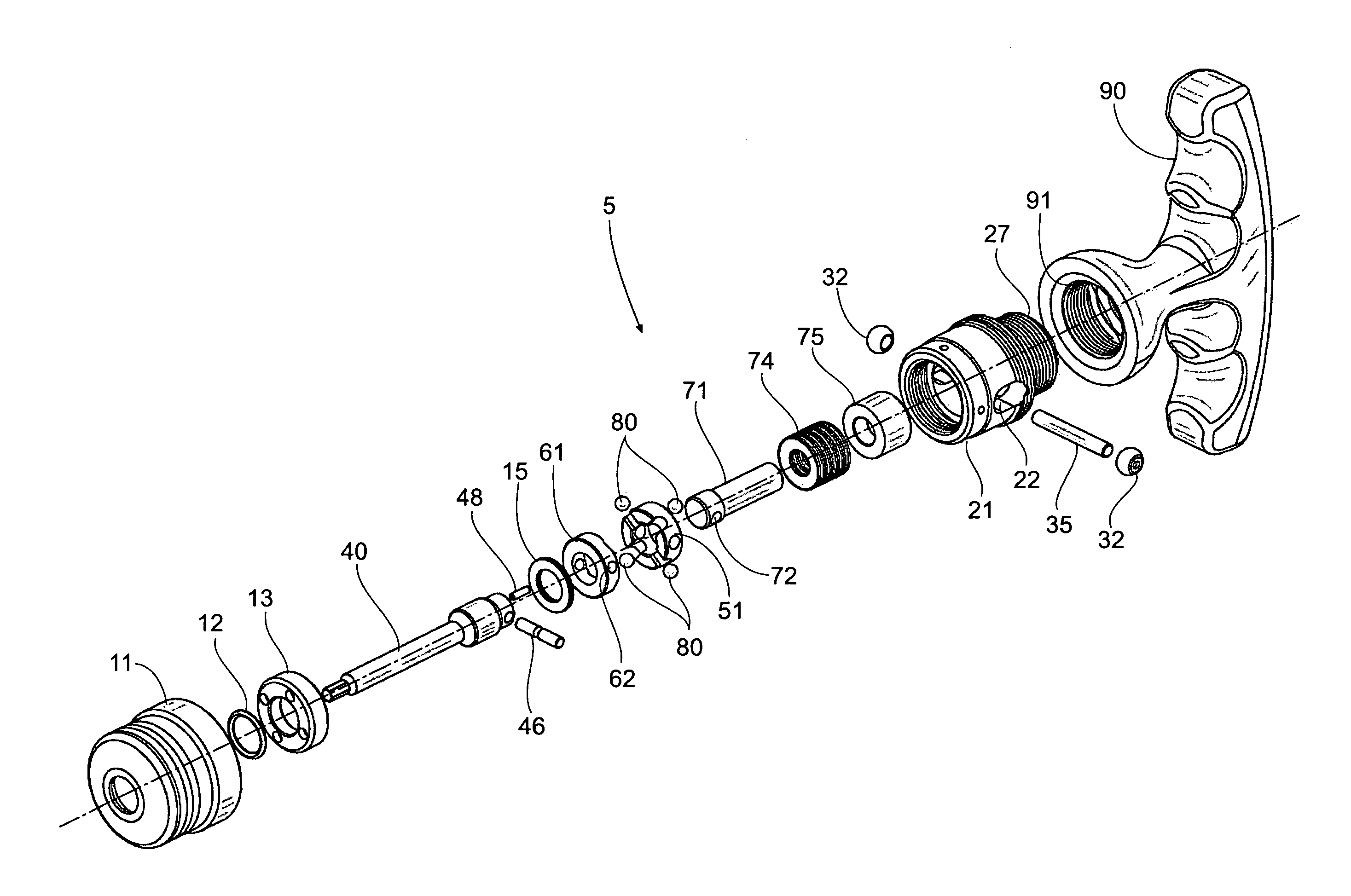
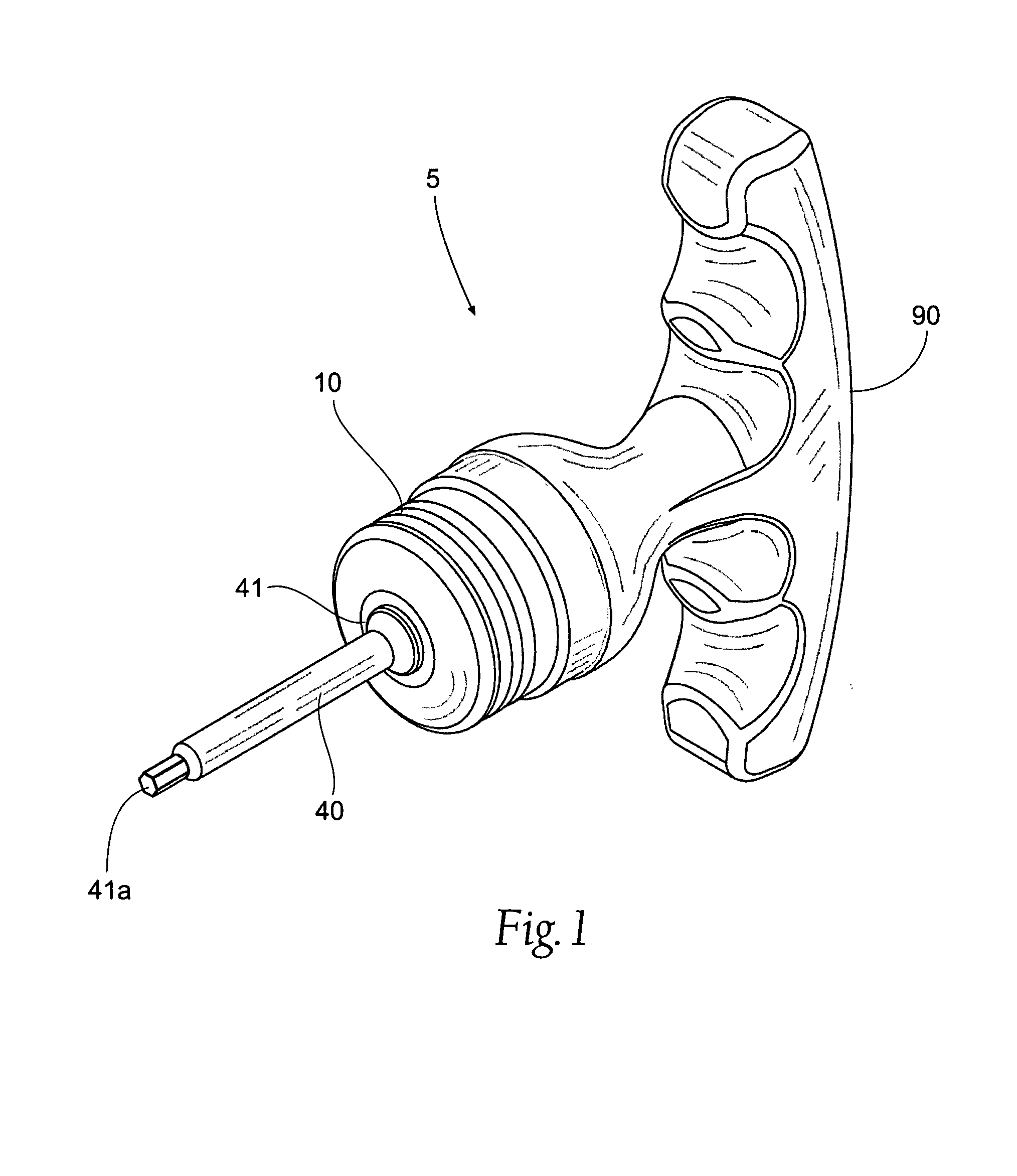
[0034]FIG. 1 is a perspective view of a torque limiting driver assembly 5 in accordance with the present invention. The assembly 5 generally consists of a handle 90, a torque limiting driver 10, and a bit or other attachment 40 comprising a shaft 41. The shaft 41 ends in a proximal end41a, which is arranged to interact with a bolt, nut, socket, screw, or other similar devices. As shown, the proximal end 41a of the bit 40 is designed as a hexagon for use as an Allan wrench type device. However, it is understood that the shaft 41 could be of any useful mechanical structure that would be used to deli...


PUM


Abstract

A clutch assembly for use with a torque limiting driver. The clutch assembly comprises two relatively rotatable clutch plates, a driving plate and a camming plate, that face one another, with a plurality of rolling members housed between the two members. The driving clutch member has a face comprising a plurality of radially spaced flat areas and a plurality of recesses interposed between the flat areas, with the recesses comprising a curvilinear base area. The second camming clutch member has a face comprising a plurality of radially spaced flat areas and a plurality of opposing downwardly sloped planar surfaces interposed between said flat areas, with the planar surfaces forming an angle. The rolling members are movable from an engaged position with the clutch members to an override position. When the rolling members are in the override position, the recesses form individual housings for the rolling members that include a gap located between the rolling members and a respective curvilinear base area.

Description

BACKGROUND OF THE INVENTION[0001]The present invention relates to mechanical drive devices, and, more specifically, to drive devices that will limit the torque being delivered from the device.[0002]Many mechanical devices are used to deliver a large amount of torque to a screw, bolt, nut, or other similar device or object. Even though there is a large amount of torque being delivered, in many situations, it is still desirous to control the precise amount of torque being delivered. For instance, too much torque may strip the object that is being driven, which would lead to the object becoming ineffective, such as stripping a bolt or screw. This is especially important in medical operations and procedures, where precision is critical, especially when working with spinal and skeletal structures and related devices. Thus, drivers have been developed to limit the amount of torque delivered to the driven object or device.[0003]Likewise, improperly calibrated or tensioned devices can also ...

Claims


Application Information

Patent Timeline
Patent Type & Authority Patents(United States)
IPC IPC(8): B25B23/14B25B23/142B25B23/157B25B23/159F16D23/00F16D43/20F16D7/00
CPCB25B23/141B25B23/1427F16D7/08F16D43/206
Inventor GAO, HUA
Owner BRADSHAW MEDICAL
Why Eureka
Try Eureka