Log debarking machine and method

a debarking machine and log technology, applied in the field of log debarking machines and methods, can solve the problems of increasing cut depth and stress, injuring the drive for rotating the head, and the contact force of hydraulic cylinders and metal springs in conventional debarking machines is not low, so as to improve the quality of debarking, reduce impact shocks, and increase the longevity of debarking machines

Inactive Publication Date: 2007-07-17
MELLOTT MFG
View PDF16 Cites 13 Cited by
  • Summary
  • Abstract
  • Description
  • Claims
  • Application Information

AI Technical Summary

Benefits of technology

[0009]During debarking the elastomer spring maintains the head in floating engagement with the log so that when recesses and projections are encountered by the head the head moves into the recesses and over the projections in a floating manner without rapid snap back or head rebound contact with the log experienced in conventional debarkers using a metal arm support spring. Logs are debarked smoothly, without impact injury to ...

Problems solved by technology

The hydraulic cylinders and metal springs in conventional debarkers do not maintain a low contact force between the head and the surface of the rotating log as the head moves into recesses in the log and over pro...

Method used


Image

  • Log debarking machine and method
  • Log debarking machine and method
  • Log debarking machine and method

Examples


Embodiment Construction

[0020]The disclosed debarker is related to the debarker disclosed in Mellott, U.S. Pat. No. 4,249,585, the disclosure of which is hereby incorporated by reference.

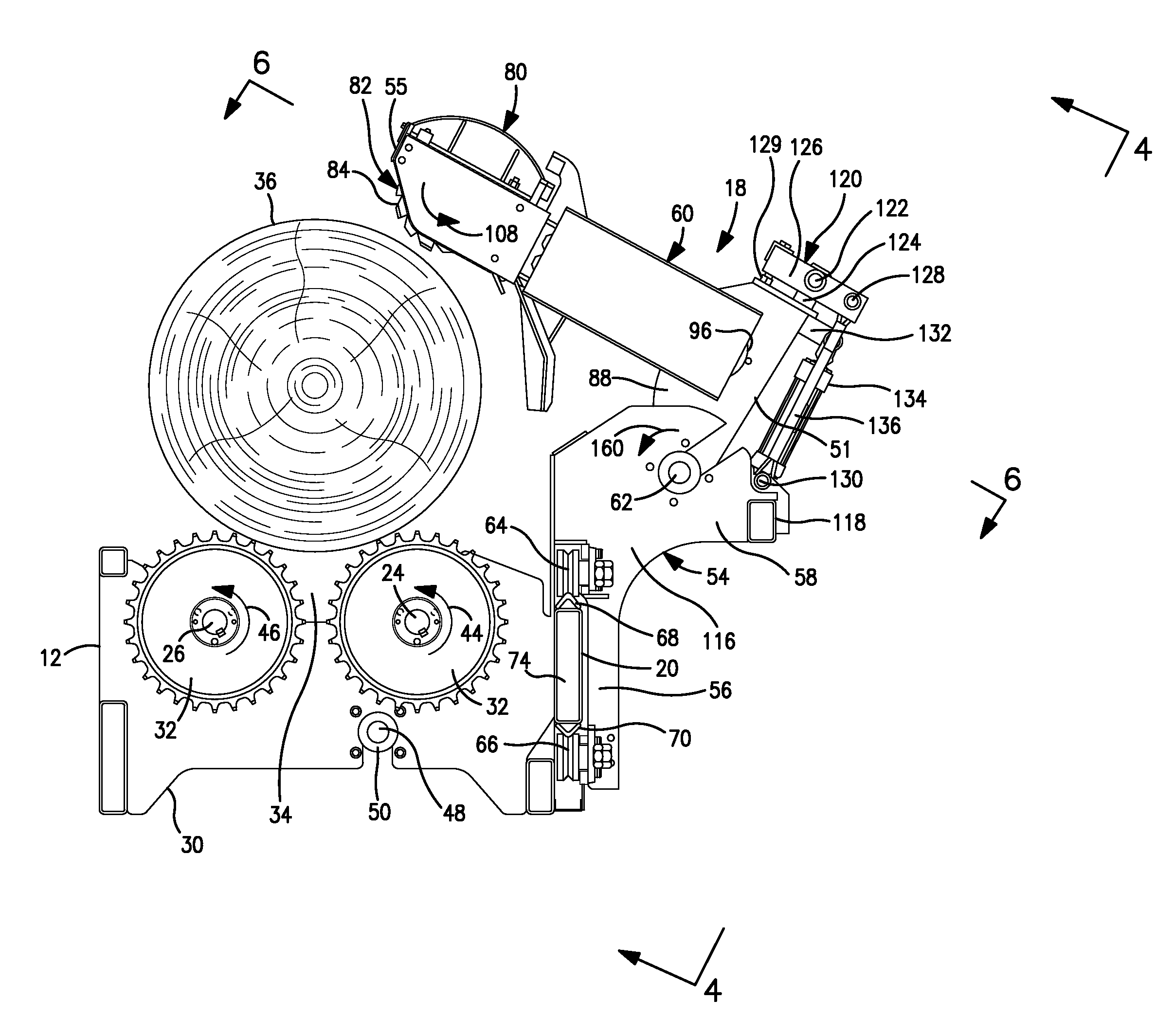
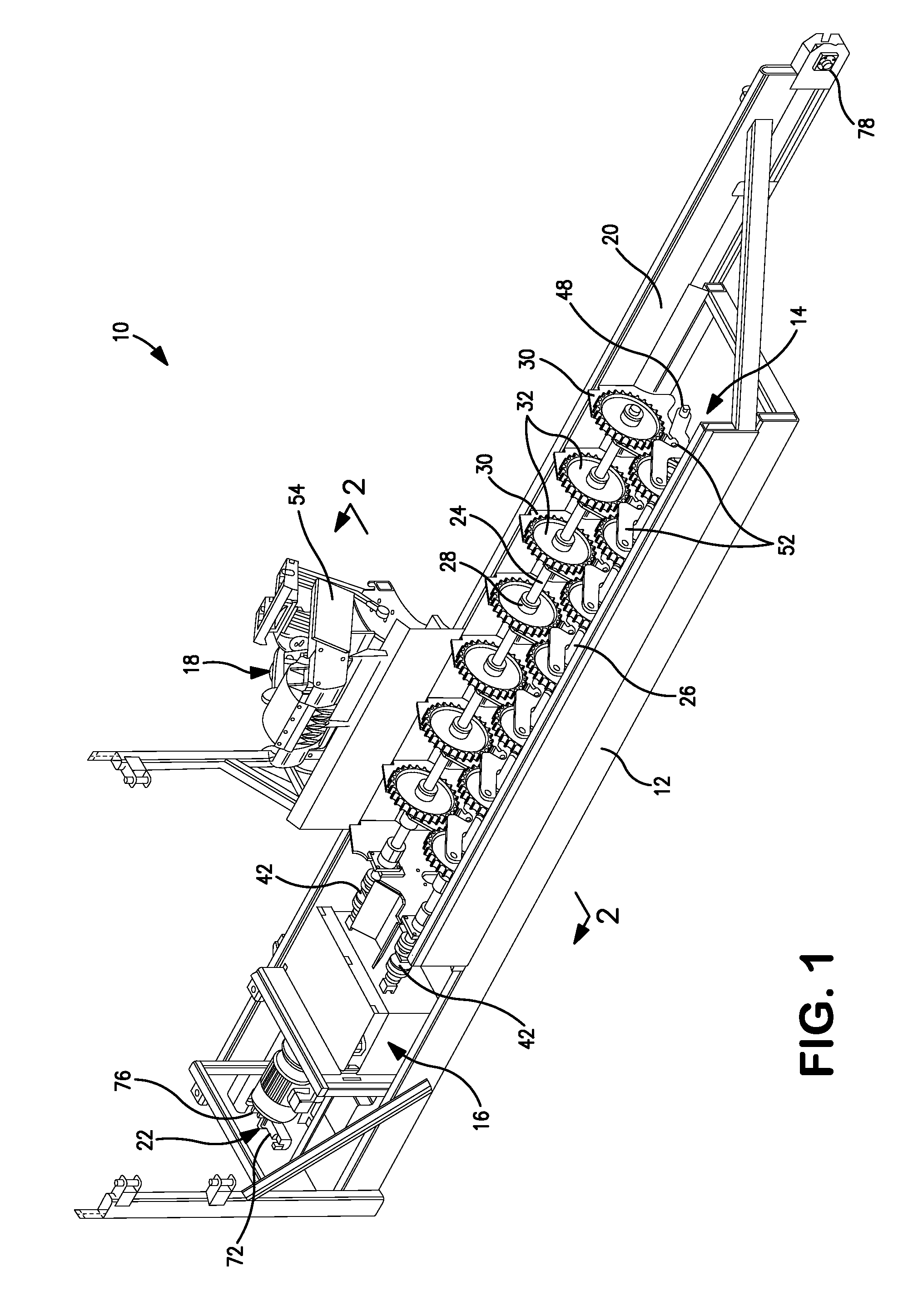
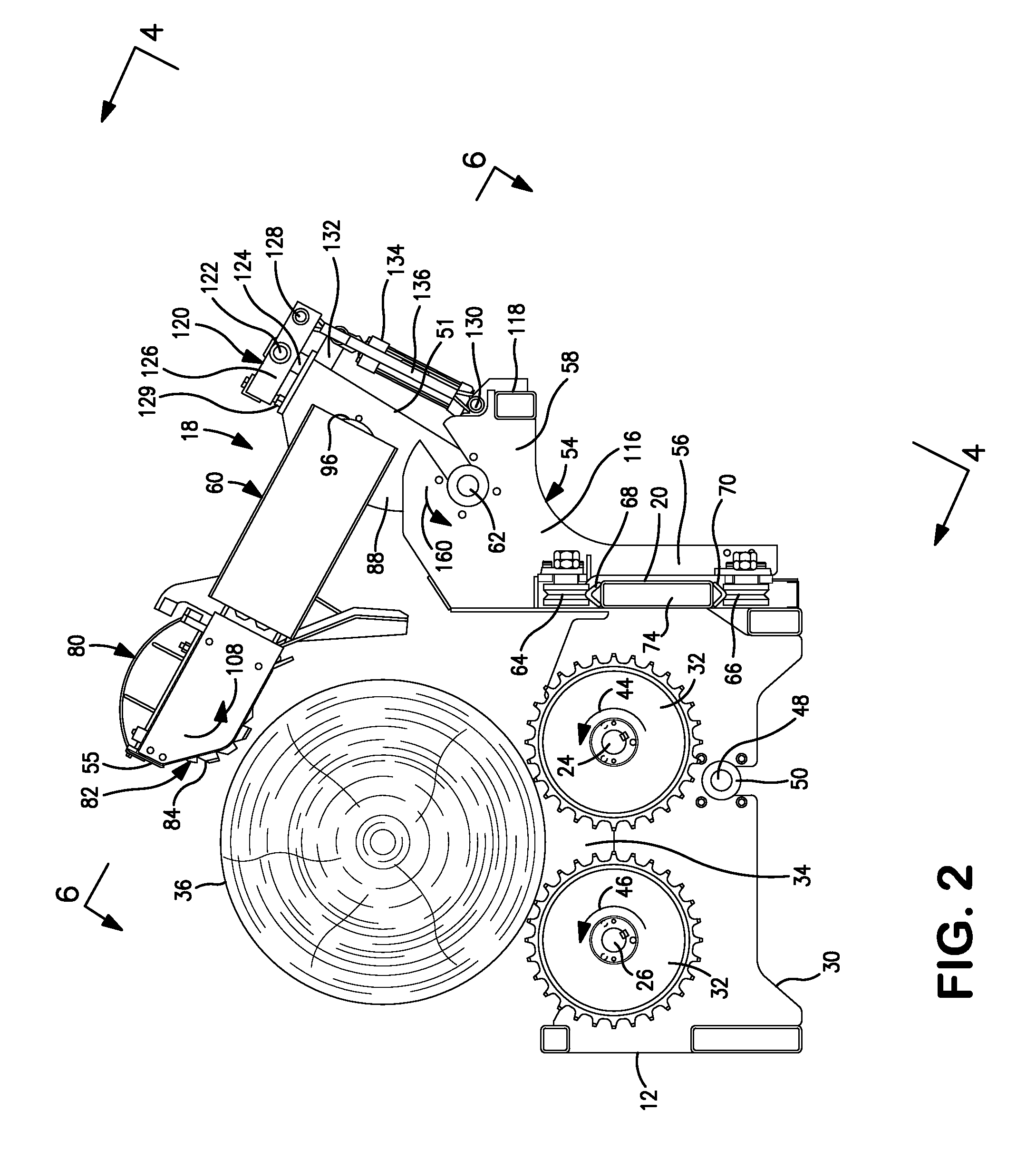
[0021]Log debarking apparatus 10 includes an elongate base 12 and a rotary log support 14 on the base. The support is powered by log support drive 16 located at one end of the base. Debarker assembly 18 is mounted on rail 20 running along one side of base 12 and extends over a log on support 14. Assembly 18 is moved back and forth along rail 20 by debarker car drive assembly 22.

[0022]Log support 14 includes two spaced, parallel log support shafts 24 and 26 extending along base 12. Shafts 24 and 26 are rotatably mounted in bearings in support plates 30 on base 12. A number of log support wheels 32 having hubs 28 are mounted on and are spaced along each shaft 24 and 26. Each wheel 32 has a plurality of cleats or projections spaced around its rim and is located adjacent to another wheel 32 on an adjacent shaft 24 or 26. The t...


PUM


Abstract

A log debarking machine includes a rotary cutter head on a debarking arm. The arm is pivotally mounted on a car so that the head engages a rotating log. The weight of the arm is supported by an elastomer spring to improve debarking engagement between the head and the log.

Description

FIELD OF THE INVENTION[0001]The invention relates to machines for removing bark from rotating logs and to methods for debarking logs.DESCRIPTION OF THE PRIOR ART[0002]Logs are conventionally debarked by rotating the logs and holding a rotary cutter head against the logs to remove bark. The rotary cutter head is mounted on a debarking arm pivotally mounted on a car located to one side of the rotating log. The arm is pivoted down to bring the rotating head into engagement with the rotating log to remove bark. Bark is preferably removed from the log by holding the head against the log with a relatively low contact force of a few hundred pounds.[0003]The weight of the heavy pivot arm is typically supported by a hydraulic cylinder and metal coil springs to prevent undesirably high contact force between the head and log. Nitrogen accumulators bias the hydraulic cylinder to hold the head against the rotating log at the desired low contact force as the diameter of the log changes.[0004]The ...

Claims


Application Information

Patent Timeline
IPC IPC(8): B27L1/00
CPCB27L1/10
Inventor MELLOTT, SAMUEL H.
Owner MELLOTT MFG
Why Eureka
Try Eureka