Drill pipe screen

a technology of drill pipe and pipe filter, which is applied in the field of drill pipe filter, can solve the problems of erosive wear on the screen components, and achieve the effect of reducing the blockage of the screen body

Inactive Publication Date: 2007-07-17
KUTRYK ED A
View PDF7 Cites 27 Cited by
  • Summary
  • Abstract
  • Description
  • Claims
  • Application Information

AI Technical Summary

Benefits of technology

[0007]A retrievable drill pipe screen is provided for intercepting debris flowing through the pipe while minimizing disturbance of the flow of the drilling fluids and which is less susceptible to wear as compared with conventional retrievable drill pipe screens.
[0008]In one embodiment of the invention, a planar support plate connects an uphole extending fish neck with a downhole extending tubular screen body whereby the plane of the support plate is aligned with the flow of the drilling fluids. The orientation of the support plate thereby minimizes the effect of the support plate on the flow of the drilling fluid from an uphole pipe, and through the screen body into a downhole pipe. At the same time, longitudinally extending planar surfaces of the planar support plate interfere with vortex motion of the drilling fluids as it enters the screen body, thereby lessening erosive wear on screen components.
[0010]Preferably, the screen body has a conical shape with a rounded, cup-shaped end to aid in cleaning of the screen body when removed from the pipe. To reinforce the integrity of the screen body, the retrievable screen may further comprise a retaining rod extending between the fish neck and the bottom of the screen body and attached thereto.
[0012]In another embodiment of the invention, a wear distributor sleeve is provided that is fit within the screen body and positioned at the uphole end thereof. The wear distributor sleeve protects the screen body against vortex motion of the drilling fluid as it enters the screen body. When a wear distributor sleeve is included in the screen, the planar support plate is attached directly to the inner sidewall surface of the wear distributor sleeve. To reduce blockage of the screen body by the wear distributor sleeve, extraneous material of the wear distributor sleeve, such as where the planar support plate is not attached and where the wear distributor sleeve does not protect against the vortex effects of the drilling fluid, may be removed.

Problems solved by technology

At the same time, longitudinally extending planar surfaces of the planar support plate interfere with vortex motion of the drilling fluids as it enters the screen body, thereby lessening erosive wear on screen components.

Method used


Image

  • Drill pipe screen
  • Drill pipe screen
  • Drill pipe screen

Examples


Embodiment Construction

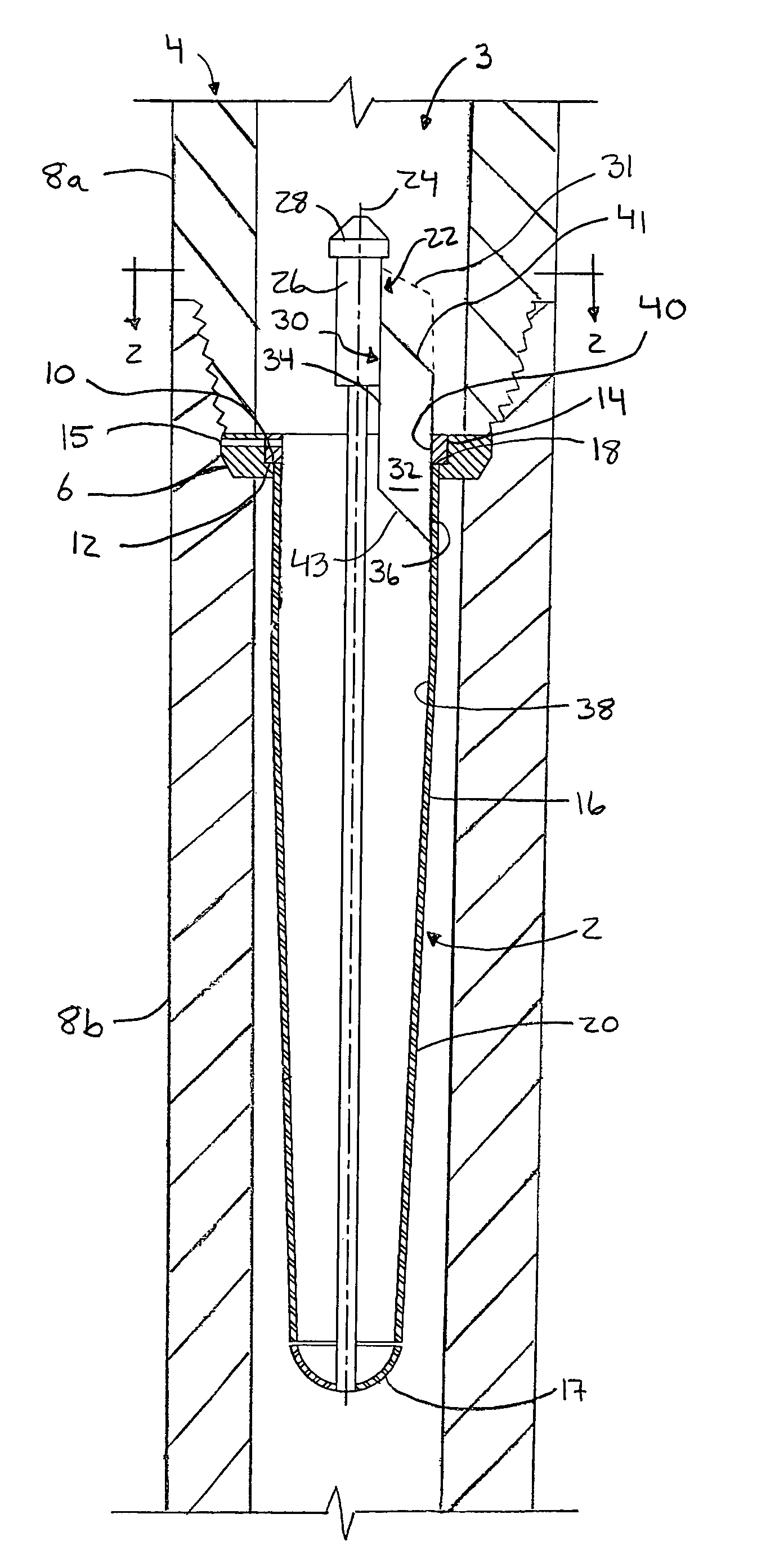
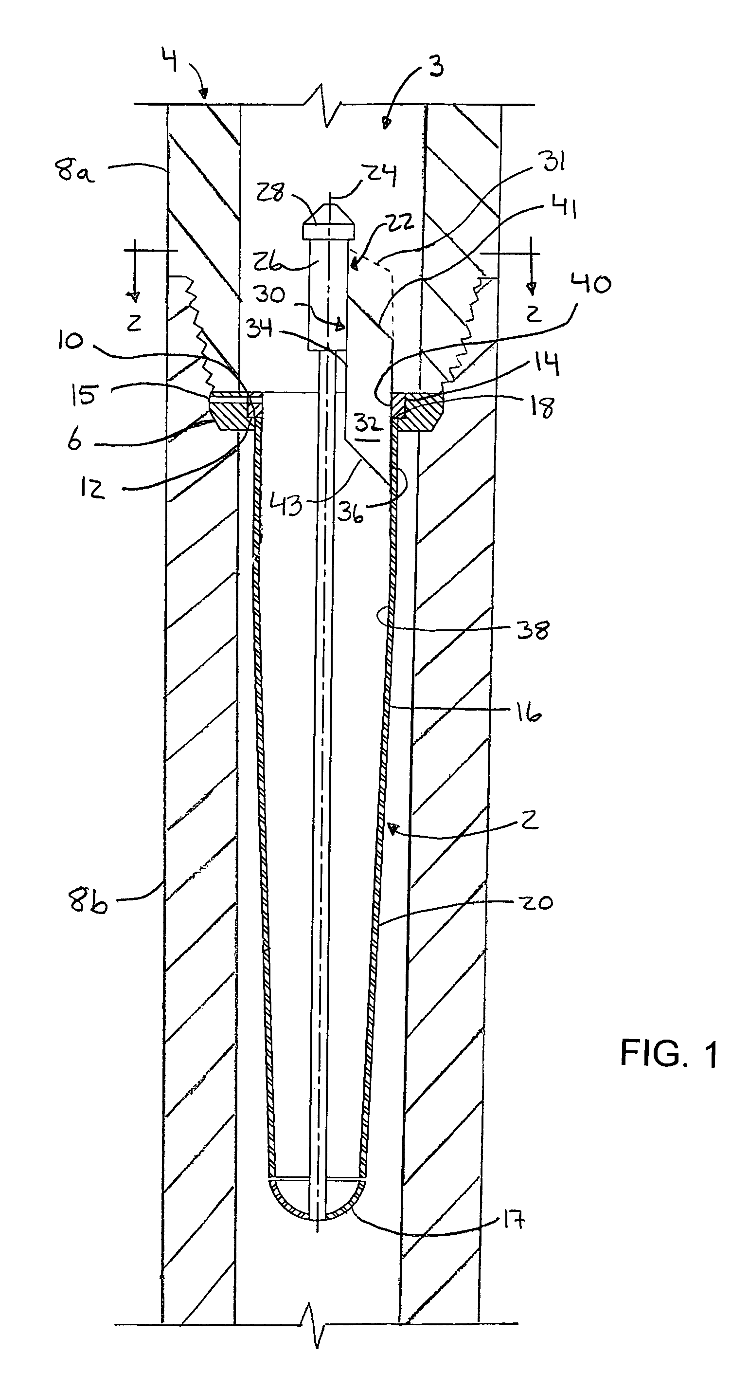
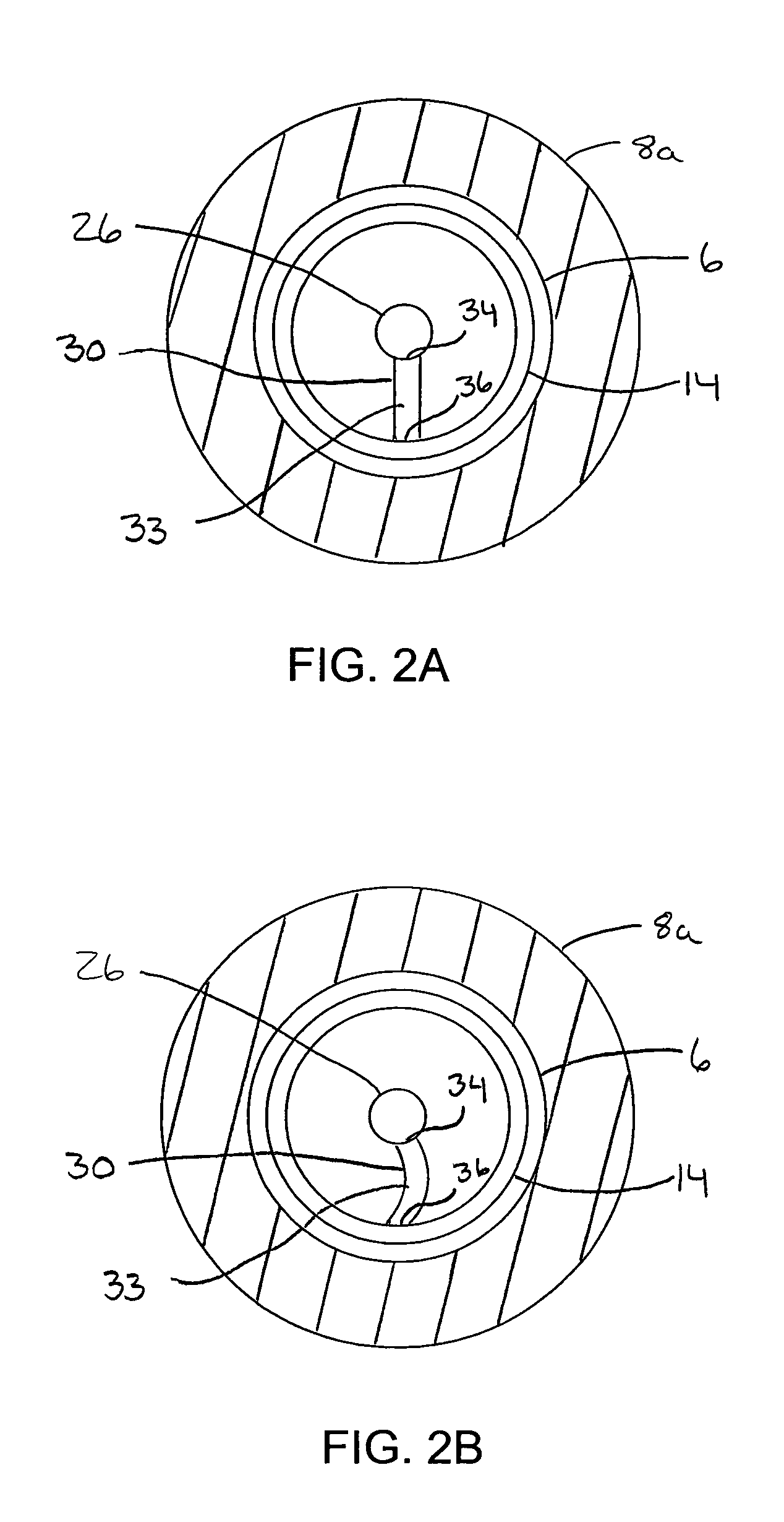
[0019]With reference to FIGS. 1 and 2, a drill pipe screen 2 is shown installed within the bore 3 of a drill pipe string 4. Generally, the components of the screen are sized according to the inner diameter of the pipe being used and are preferably constructed of wear and corrosion resistant material such as 316 stainless steel. The components are securely attached to each other as indicated herein by any suitable means known in the art, such as, for example, by welding.

[0020]With reference to FIG. 1, the screen 2 comprises an elongate and perforated tubular screen body 16 which is securely attached to a screen support ring 14 and extends downhole therefrom. An uphole open top end 18 of the screen body 16 abuts to a downwardly facing surface 12 of the screen support ring 14.

[0021]The drill pipe screen 2 is adapted for support upon an annular mounting collar 6 that is anchored within the bore of the pipe. Typically, the mounting collar is sandwiched within an annular recess defined be...


PUM


Abstract

A retrievable drill pipe screen is adapted for releasable connection within a drill pipe string. The screen has a planar support plate for connecting a perforated tubular screen body to a fish neck wherein the plane of the planar support plate is generally parallel to the axis of the screen body. The orientation of the planar support plate provides minimal resistance to fluid flowing into the screen body while also reducing vortex effects that cause wear of screen components. Preferably, a wear distributor sleeve is fit within the screen body for protecting against wear of the screen caused by fluid flow and a retaining rod can secure the bottom of the screen body to the fish neck in the event that a lower portion of the screen body becomes detached.

Description

CROSS-REFERENCE TO RELATED APPLICATIONS[0001]This application claims the benefit of U.S. provisional application No. 60 / 524,868, filed Nov. 26, 2003, the entirety of which is herein incorporated by reference.FIELD OF THE INVENTION[0002]The invention relates to screens and in particular to retrievable screens for fitting within the bore of a pipe, such as a drill pipe.BACKGROUND OF THE INVENTION[0003]In the drilling of a subterranean rock formation, tubing such as a drill stem assembly or drill pipe string conducts drill mud or drilling fluids downhole to tools such as mud motors or a drill bit. Drilling fluids are circulated downhole through the tubing for a variety of purposes including carrying drill cuttings up an annulus about the tubing and to the surface for screening, reconditioning and recirculation. In drilling with coiled tubing, mud motors are powered by the flow of drilling fluids and are used to rotate the bit. In conventional rotary drilling, the drill pipe string is u...

Claims


Application Information

Patent Timeline
Patent Type & Authority Patents(United States)
IPC IPC(8): E21B43/38B01D35/02B01D35/28E21B21/00
CPCB01D35/02E21B21/002B01D2201/02
Inventor KUTRYK, ED A.
Owner KUTRYK ED A
Why Eureka
Try Eureka