Ocean wave energy converter

a converter and ocean wave technology, applied in the direction of electric generator control, machines/engines, mechanical equipment, etc., can solve the problems of increasing the cost, increasing the cost, and difficult to achieve, and achieve the effect of increasing the tension and increasing the length

Inactive Publication Date: 2007-07-17
OLSON CHRIS F
View PDF17 Cites 137 Cited by
  • Summary
  • Abstract
  • Description
  • Claims
  • Application Information

AI Technical Summary

Problems solved by technology

There are many problems that have prevented ocean generators from going into production.
They have numerous moving parts that are exposed to the salt water that will have a limited life under harsh and corrosive conditions.
Many are tightly anchored to the ocean floor, which is very expensive (one float to one or more anchors).
When an anchor is pulled from the side it is very strong, but when an anchor is pulled straight up, it must be much stronger and deeper, which adds greatly to the cost.
When an apparatuses is mounted solidly in a fixed position or relationship to the ocean floor, e.g., tightly fixed by an anchor, then it must be continuously adjusted for the different height in the tide, which is very difficult to do.
Since waves have a long distance between them, many apparatuses will not produce power between wave motions.
The ocean waves have enormous energy, but there are many problems with trying to convert it to electricity.
The salt water is very corrosive and sea life attaches itself to everything.
Trying to make anything permanently fixed in place in the ocean is almost impossible.

Method used


Image

  • Ocean wave energy converter
  • Ocean wave energy converter
  • Ocean wave energy converter

Examples


Embodiment Construction

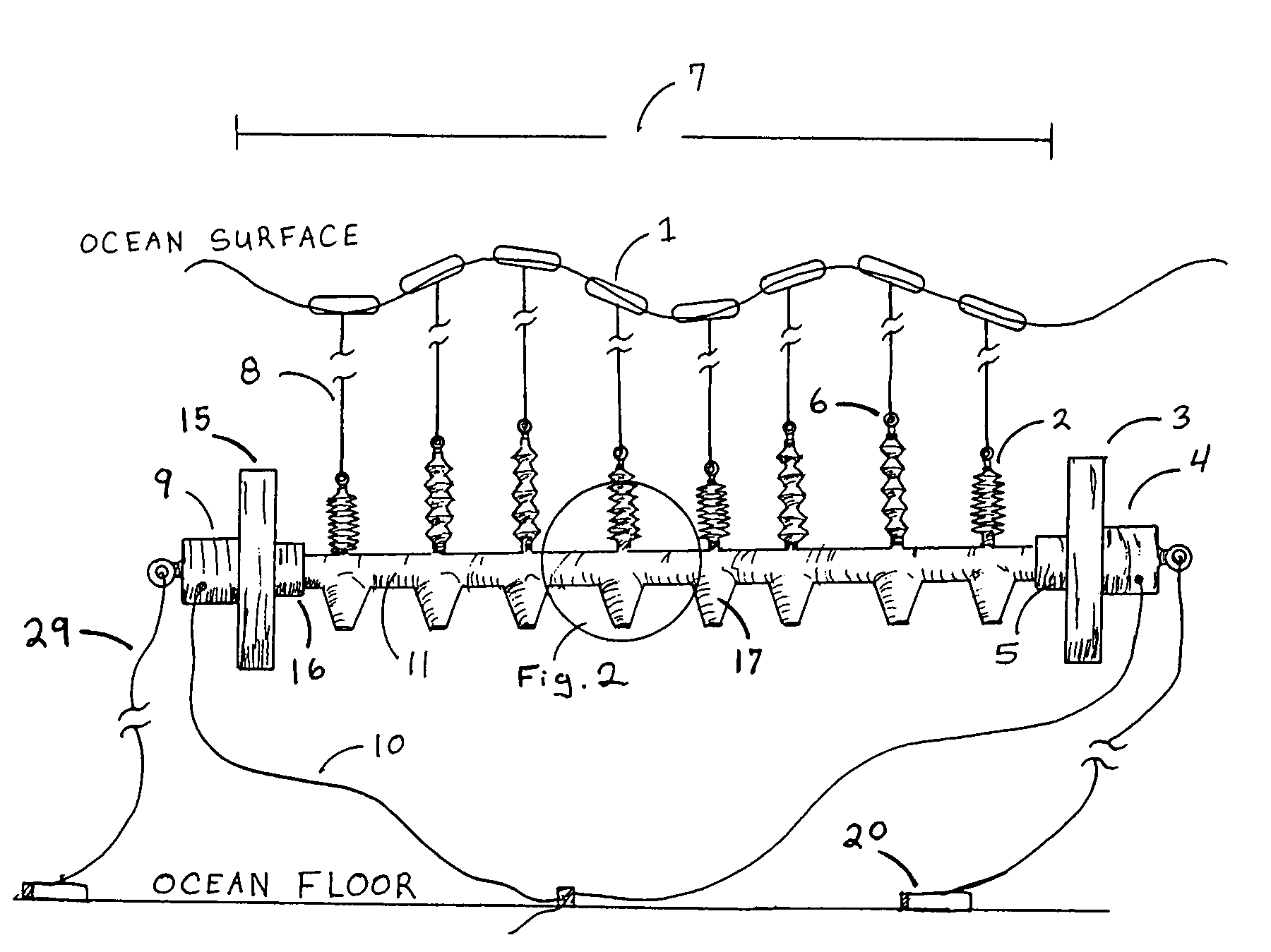
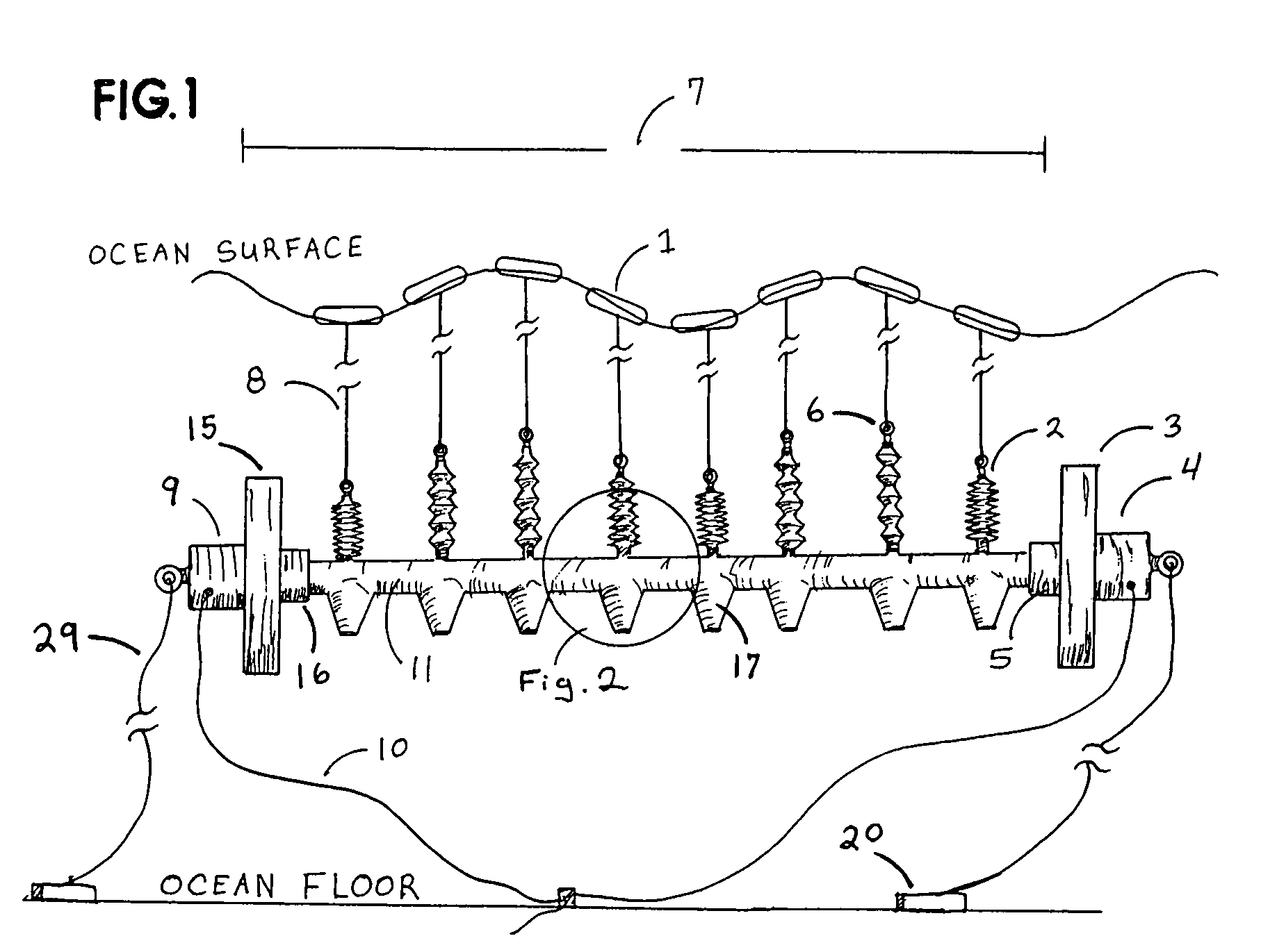
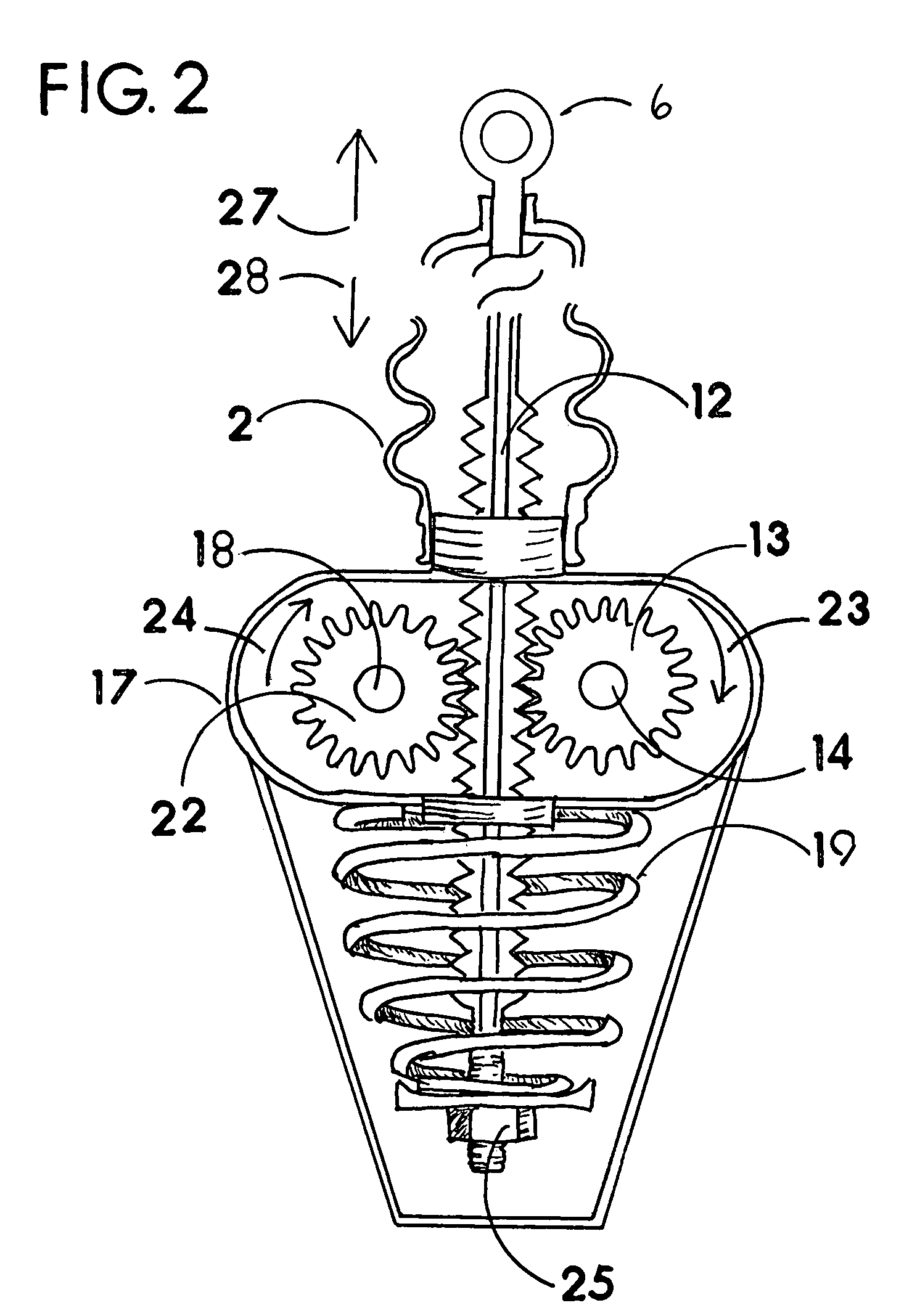
[0019]The apparatus takes into account the difficult obstacles that have prevented other devices from being successfully used as power generators. These are some of the problems this apparatus solves: (A) The apparatus has no moving parts that are exposed to the salt water. (B) The beam uses its own mass to act against the pulling forces of the floats, so it does not having to be tightly fastened to the ocean floor. (C) The beam does not have to mechanically adapt to the change in height of the tide. (D) The beam will be submerged deep enough so that ships cannot damage it. (E) The machine components may make energy in both directions as the individual floats add and release tension on the retention springs. (F) The beam is protected from storms and large waves because it is well below the ocean surface. (G) The huge cost saving of not having to anchor tightly to the ocean floor will make this apparatus more cost effective. (H) One anchor can hold numerous floats. (I) Beachfront pro...


PUM


Abstract

A long cylinder shaped beam is submerged in the ocean and suspended horizontally by multiple floats for converting ocean wave energy. The long length (at least the distance of the crest of two waves) and heavy weight of the beam, give the floats something stable to pull against. The weight of the beam pulling at the floats is transferred back and forth, as the ocean swells move over the beam, which activate machine components that may be installed in the beam, the floats or with rods connecting the floats to the beam. An individual float will not lift the beam except when the tide raises all the floats. The floats will pull and release the tension of the weight of the beam at randomly different times. The shape of the beam is straight. The ocean surface is continuously curving up and down and the beam will not bend to the shape of the ocean surface, but the floats will mimic the undulating or curvy shape of the ocean surface, and that motion actives the machine. The energy of the floats pulling against the elongated component is then turned into mechanical or hydraulic energy.

Description

RELATED APPLICATIONS[0001]This application claims the benefit and priority to provisional application No. 60 / 798,002 filed May 5, 2006 and entitled “Ocean Wave Energy Converter” and which is incorporated herein by reference.FIELD OF INVENTION[0002]This invention pertains to an apparatus and method for converting wave motion into other forms of energy.BACKGROUND OF INVENTION[0003]Inventors have been trying to figure how to extract energy from the ocean for more than 150 years.[0004]U.S. Pat. No. 4,408,454, issued 1983, discloses a fluid coupled wave generator array with sub sea structure wherein a sub sea support structure is coupled to floats in a Hagen array. This invention has many differences and problems, such as, many moving parts exposed to the salt water, it has to be tightly anchored or solidly fastened to the ocean floor, ships can collide with the apparatus. It does not use its own weight to pull against instead it pulls on the ocean floor. The floats are responsive to the...

Claims


Application Information

Patent Timeline
Patent Type & Authority Patents(United States)
IPC IPC(8): F03B13/10
CPCF03B13/1885Y02E10/38Y02E10/30
Inventor OLSON, CHRIS F.
Owner OLSON CHRIS F
Why Eureka
Try Eureka