Apparatus for and method of cable diagnostics utilizing time domain reflectometry

a technology of time domain and reflectometry, applied in the field of data communication, to achieve the effect of high accuracy

Active Publication Date: 2007-07-17
TEXAS INSTR INC
View PDF11 Cites 36 Cited by
  • Summary
  • Abstract
  • Description
  • Claims
  • Application Information

AI Technical Summary

Benefits of technology

[0011]The present invention is a novel mechanism for performing high accuracy cable diagnostics. The mechanism can be incorporated into a conventional Ethernet transceiver, such as a Gigabit Ethernet transceiver, with minimal modification thus eliminating the need to use special and costly cable measurement equipment. The cable diagnostic mechanism enables the detection and identification of cables faults, estimation of cable length, identification of cable topology and identification of load and irregular impedance on metallic paired cable, such as twisted pair and coaxial cables.
[0012]The cable diagnostics mechanism of the present invention uses a time domain reflectometry (TDR) mechanism whereby pulses are transmitted and any resulting signal reflections are detected and analyzed to generate diagnostic information about the channel. The shape of the pulses transmitted by the TDR mechanism is programmable and can be optimized in accordance with the particular channel characteristics such as cable length and type, including the transmitter and receiver paths. Optimizing the transmitted pulse shape results in optimal analysis for faults located anywhere along the cable.
[0014]Further, the time domain reflectometry based cable diagnostic mechanism of the present invention is adapted to operate in the case where the channel comprises high pass filters. The use of high pass filters in the channel causes the amplitude of the reflected signals to be somewhat reduced. The present invention includes techniques to overcome this problem.
[0016]The TDR mechanism of the present invention provides several advantages including: (1) the reuse of hardware already available on conventional transceivers for transmission of the TDR pulse; (2) use of a programmable pulse shape that can best be fitted to enhance performance given a particular channel model, where the channel model includes any filtering performed by the transmitter or receiver; (3) use of a programmable detection unit optimized to enhance detection given a channel model and transmitted pulse shape; (4) support of cable diagnostics on high pass filter channels; (5) use of an averaging mechanism that enables reliable detection in noisy environments; and (6) making a series of TDR observations using different types of transmitted pulses on each measurement such that the total observation covers the entire cable length, where longer pulses are better for identifying far located faults, while short pulses are better for locating close cable faults (since the blind-spot region caused by the transmitted pulse width is minimized).

Problems solved by technology

Such irregularities may be caused by defective, broken or loose connectors, damaged cables or a variety of other faults.

Method used


Image

  • Apparatus for and method of cable diagnostics utilizing time domain reflectometry
  • Apparatus for and method of cable diagnostics utilizing time domain reflectometry
  • Apparatus for and method of cable diagnostics utilizing time domain reflectometry

Examples


Embodiment Construction

Notation Used Throughout

[0032]The following notation is used throughout this document.

[0033]

TermDefinitionA / DAnalog to Digital ConverterAGCAutomatic Gain ControlASICApplication Specific Integrated CircuitDCDirect CurrentDFEDecision Feedback EqualizerDSPDigital Signal ProcessorFFEFeed Forward EqualizerFPGAField Programmable Gate ArrayGEGigabit EthernetHDLHardware Description LanguageHPFHigh Pass FilterICIntegrated CircuitLUTLookup TablePGAProgrammable Gain AmplifierRFRadio FrequencySTPShielded Twisted PairTDRTime Domain ReflectometryUTPUnshielded Twisted Pair

DETAILED DESCRIPTION OF THE INVENTION

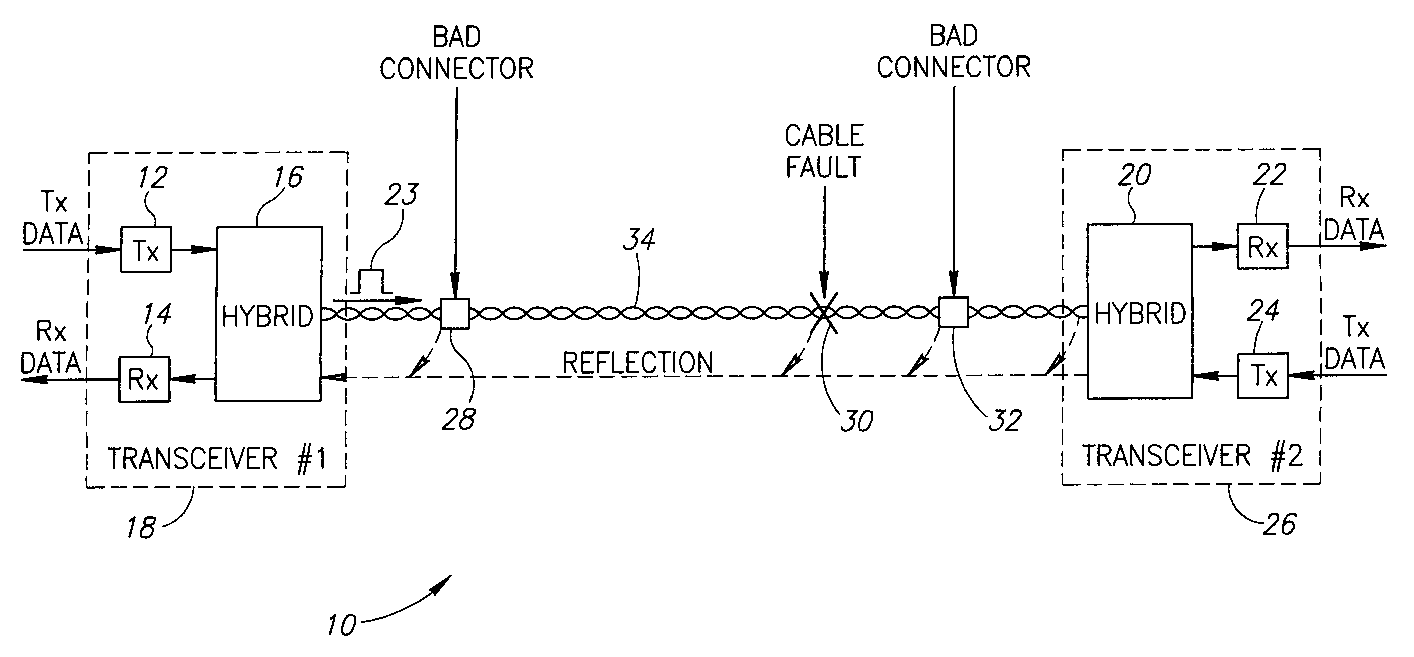
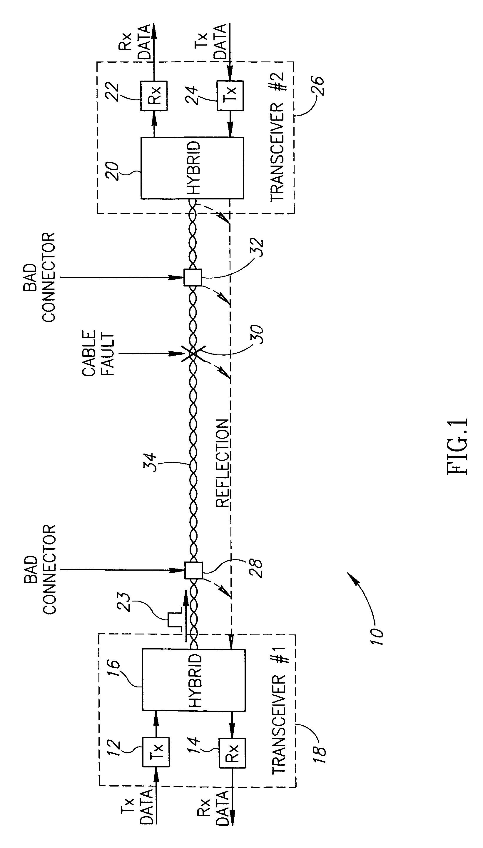
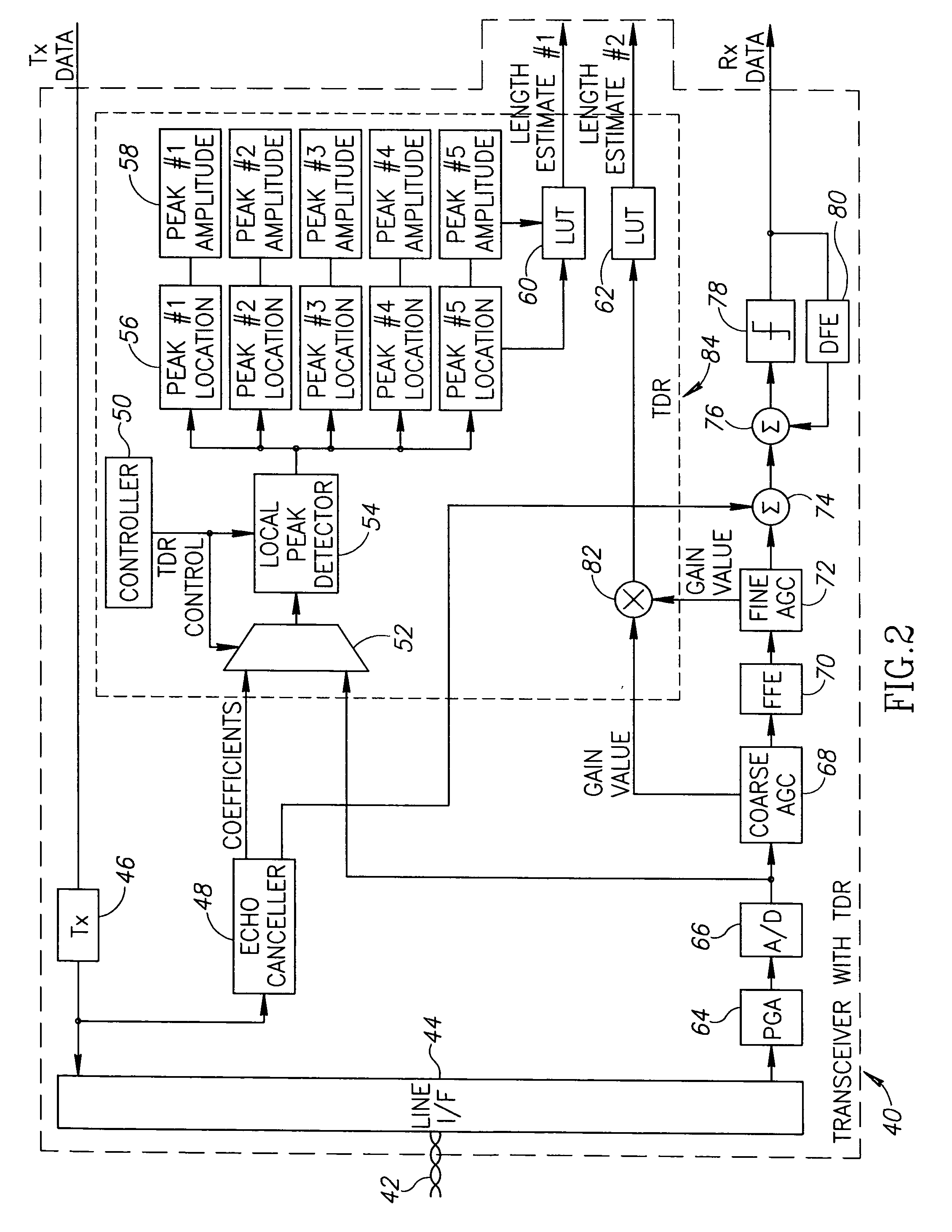
[0034]The present invention provides a novel mechanism for performing high accuracy cable diagnostics. The mechanism utilizes time domain reflectometry (TDR) to detect and identify cable faults, perform estimations of cable length, identify cable topology, identify load and irregular impedance on metallic paired cable, such as twisted pair and coaxial cables. The TDR mechanism transmits pulses...


PUM


Abstract

A novel mechanism for performing high accuracy cable diagnostics. The mechanism utilizes time domain reflectometry (TDR) to detect and identify cable faults, perform estimations of cable length, identify cable topology, identify load and irregular impedance on metallic paired cable, such as twisted pair and coaxial cables. The TDR mechanism transmits pulses whose shapes are programmable and analyzes the signal reflections. The shapes of the pulses transmitted can be optimized in accordance with the channel characteristics. Further, the TDR mechanism is adapted to operative in the presence of high pass filters in the channel.

Description

REFERENCE TO PRIORITY APPLICATION[0001]This application claims priority to U.S. Provisional Application Ser. No. 60 / 653,179, filed Feb. 14, 2005, entitled “Time Domain Reflectometry Methods for Cable Diagnostics,” incorporated herein by reference in its entirety.FIELD OF THE INVENTION[0002]The present invention relates to the field of data communications and more particularly relates to an apparatus for and method of performing high accuracy cable diagnostics, including, for example, detection of cable faults, cable length, utilizing time domain reflectometry.BACKGROUND OF THE INVENTION[0003]Modern network communication systems are generally of either the wired or wireless type. Wireless networks enable communications between two or more nodes using any number of different techniques. Wireless networks rely on different technologies to transport information from one place to another. Several examples include, for example, networks based on radio frequency (RF), infrared, optical, et...

Claims


Application Information

Patent Timeline
Patent Type & Authority Patents(United States)
IPC IPC(8): G01R31/11
CPCG01R31/11H04B3/46
Inventor WAJCER, DANIELSOMMER, NAFTALISEMEL, NOHIK
Owner TEXAS INSTR INC
Why Eureka
Try Eureka