
Optical analyzer for improving resolution of a time-varying spectrum and method therefor

a technology of optical analyzer and time-varying spectrum, which is applied in the direction of optical radiation measurement, instruments, spectrometry/spectrophotometry/monochromators, etc., can solve the problems of increasing the overall operating cost, increasing the fabrication cost of the spectral analysis system, and increasing the complexity of the amplifier. , to achieve the effect of reducing the measurement time of the spectrum, enhancing the resolution, and reducing the noise influence of dri

Active Publication Date: 2007-07-17
SAMSUNG ELECTRONICS CO LTD
View PDF8 Cites 24 Cited by
  • Summary
  • Abstract
  • Description
  • Claims
  • Application Information

AI Technical Summary

Benefits of technology

[0010]It is a feature of an embodiment of the present invention to provide a spectroscopic analyzing apparatus that enhances the resolution of a spectrum.
[0023]Further, since an embodiment of the inventive analyzing method decreases the measurement time of the spectrum, noise influence due to drift is reduced compared with the related art analyzing method.

Problems solved by technology

Thus, as the number of channels increases, fabrication cost of the spectral analysis system increases.
The plurality of amplifiers complicates the system, and the addition of channels causes the overall operating costs to be increased.
However, if the spectral amplitudes of the specimen vary across the spectrum, the signal-to-noise ratio (SNR) may not be sufficiently high to analyze the entire spectrum.

Method used


Image

  • Optical analyzer for improving resolution of a time-varying spectrum and method therefor
  • Optical analyzer for improving resolution of a time-varying spectrum and method therefor
  • Optical analyzer for improving resolution of a time-varying spectrum and method therefor

Examples


Embodiment Construction

[0030]Korean Patent Application No. 2003-85825, filed on Nov. 28, 2003, in the Korean Intellectual Property Office, and entitled: “Optical Analyzer for Improving Resolution of Time-varying Spectrum and Device Therefor,” is incorporated by reference herein in its entirety.

[0031]The present invention will now be described more fully hereinafter with reference to the accompanying drawings, in which exemplary embodiments of the invention are shown. The invention may, however, be embodied in different forms and should not be construed as limited to the embodiments set forth herein. Rather, these embodiments are provided so that this disclosure will be thorough and complete, and will fully convey the scope of the invention to those skilled in the art. Like reference numerals refer to like elements throughout.

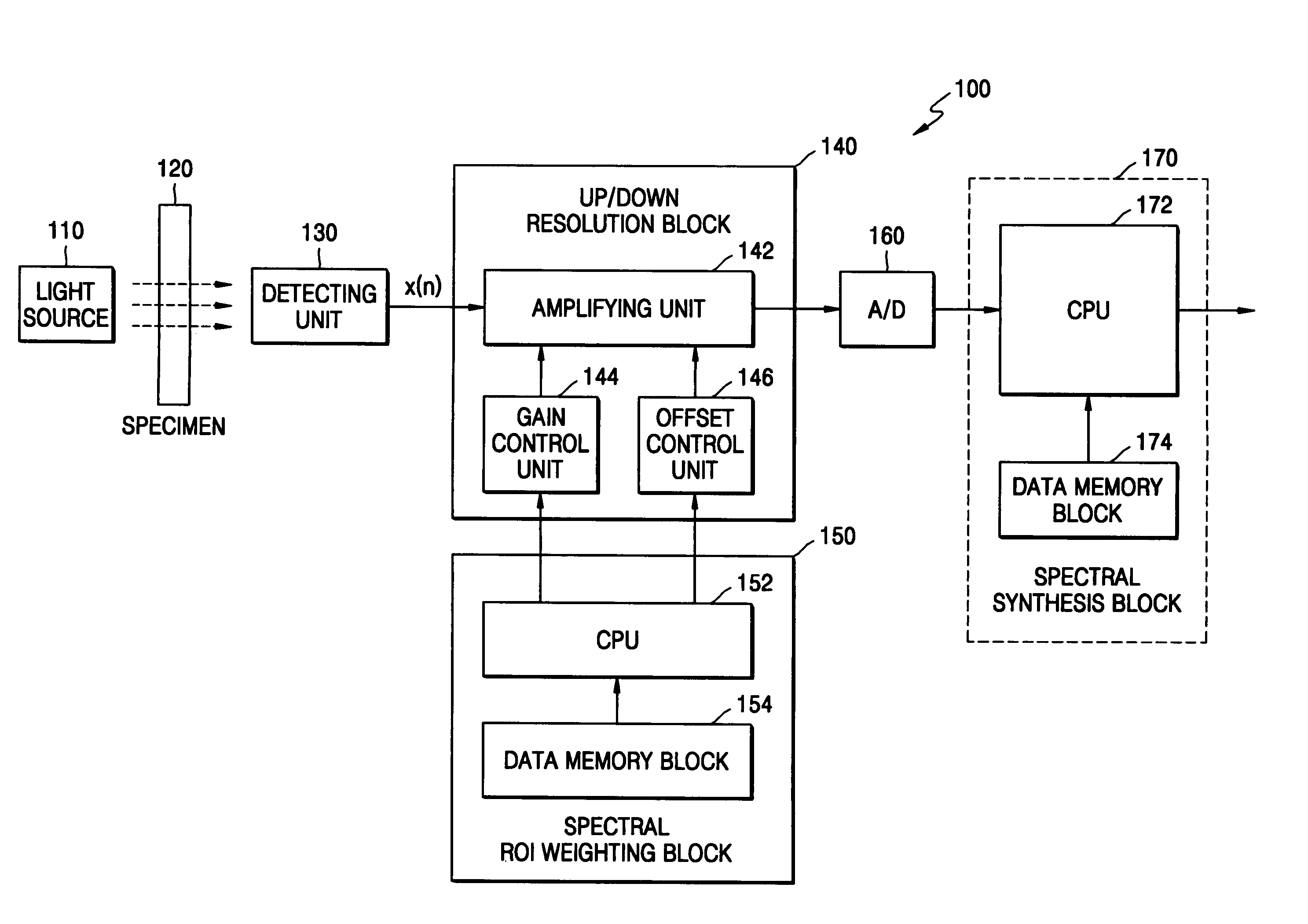
[0032]FIG. 1 illustrates a block diagram of a spectroscopic analyzing apparatus according to an embodiment of the present invention. Referring to FIG. 1, a spectroscopic analyzer 100 ...


PUM

PropertyMeasurementUnit
opticalaaaaaaaaaa
optical spectrumaaaaaaaaaa
spectroscopic analyzeraaaaaaaaaa

Abstract

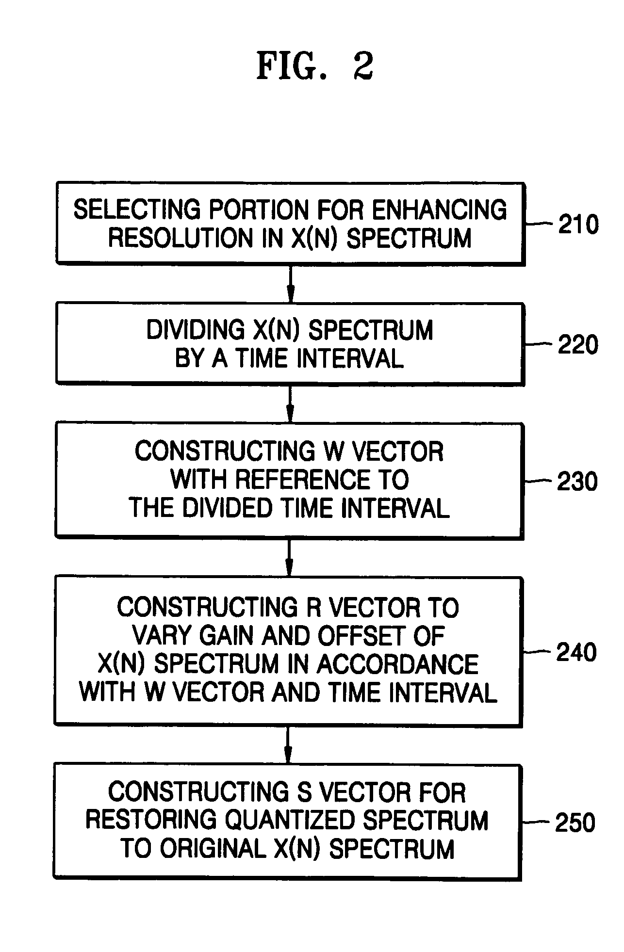
An analyzing method and system includes projecting light onto a specimen, detecting an optical spectrum from the specimen, dividing the detected optical spectrum by a predetermined time interval, applying a weighting vector and a gain and offset vector to the divided spectra to generate a resolution vector, quantizing an analog signal of the resolution vector to a digital signal, and applying a synthesis vector to the quantized spectra to restore the quantized spectra to a size of the optical spectrum. A spectrum having a large amplitude difference is temporally divided and is analyzed by applying different resolutions to individual time intervals. Spectral portions of the spectrum having relatively small peak amplitudes are selected as a region of interest (ROI) to be modified.

Description

BACKGROUND OF THE INVENTION[0001]1. Field of the Invention[0002]The present invention relates to a spectroscopic analyzing apparatus and method. More particularly, the present invention relates to a method and apparatus for improving a resolution of a time-varying spectrum.[0003]2. Description of the Related Art[0004]In a spectroscopic analyzing method, light is projected onto a specimen and a reference material, respectively. The respective detected spectrum amplitudes are compared, and the components of the specimen are analyzed. In reviewing an entire spectral band of a specimen, a main component of the specimen has a meaningful spectrum, which is isolated from the remaining components. By analyzing the amplitude of this meaningful spectrum, the components of the specimen and the content of each of the components can be estimated.[0005]One conventional spectroscopic analyzing method uses infrared radiation from a lamp passing through selected filters so that a specific frequency ...

Claims


Application Information

Patent Timeline
Patent Type & Authority Patents(United States)
IPC IPC(8): G01J3/40G06F15/00G01J3/28G01J3/02G01N21/31G01N21/59
CPCG01N21/31G01J3/28
Inventor HAN, WAN-TAEK
Owner SAMSUNG ELECTRONICS CO LTD
Learn More