
Unobtrusive measurement system for bioelectric signals

a bioelectric signal and unobtrusive technology, applied in the field of bioelectric signal measurement system, can solve the problems of inability to maintain the necessary electrical contact, alternative forms cannot overcome the fundamental limitation of needing to directly contact the skin, and patients are not comforted, so as to achieve convenient, unobtrusive and effective ways, and little or no intervention.

Active Publication Date: 2007-07-17
QUANTUM APPLIED SCI & RES
View PDF117 Cites 146 Cited by
  • Summary
  • Abstract
  • Description
  • Claims
  • Application Information

AI Technical Summary

Benefits of technology

"The present invention is a system for measuring bioelectric signals from individuals without interfering with their daily activities. The system uses multiple sensors placed on an object that the individual rests against, such as a chair or bed. The sensors are positioned away from the individual's skin to ensure proper functioning. The sensor system can be integrated into the object, making it convenient and comfortable for the individual to have their bioelectric signals measured. This invention provides a non-invasive and effective way to measure bioelectric signals, with minimal intervention required from the individual."

Problems solved by technology

Obviously, this requires preparation and application time, while being quite discomforting to the patient.
Although attempts have been made to construct new types of resistive electrodes, such as making an electrically conductive fabric, providing a miniature grid of micro-needles that penetrate the skin, and developing chest belt configurations for heart related measurements or elasticized nets with resistive sensors making contact via a conductive fluid for head related measurements, these alternative forms do not overcome the fundamental limitation of needing to directly contact the skin.
This limitation leads to an additional concern regarding the inability to maintain the necessary electrical contact based on differing physical attributes of the patient, e.g. amount of surface hair, skin properties, etc.
The electrodes associated with these types of sensors are strongly affected by lift-off from the skin, particularly since the capacitive sensors were not used with conducting gels.
As a result, capacitive sensors have not been found to provide any meaningful benefits and were not generally adopted over resistive sensors.
Specifically, a truly unobtrusive measurement system which does not require patient preparation is needed.

Method used


Image

  • Unobtrusive measurement system for bioelectric signals
  • Unobtrusive measurement system for bioelectric signals
  • Unobtrusive measurement system for bioelectric signals

Examples


Embodiment Construction

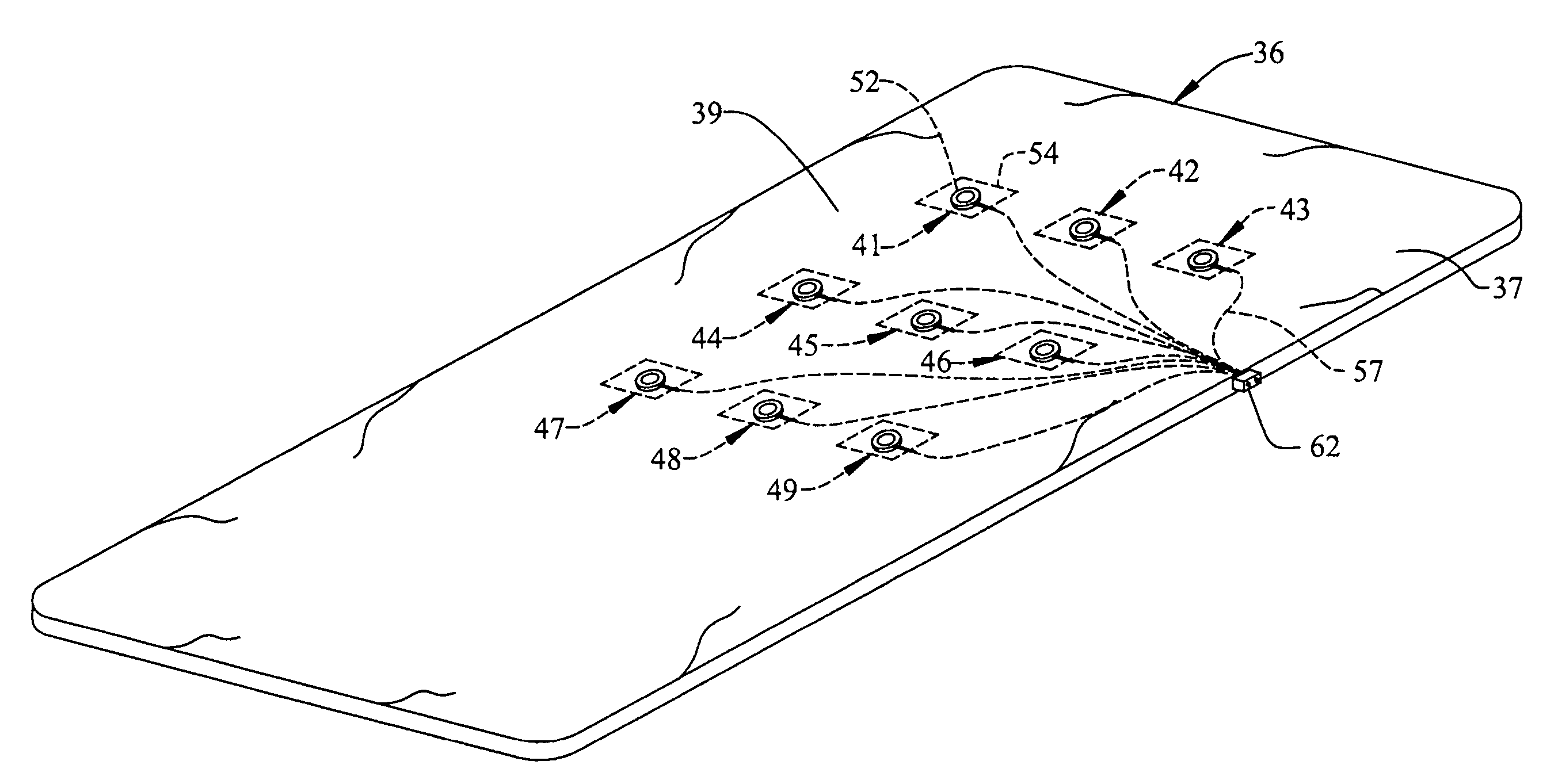
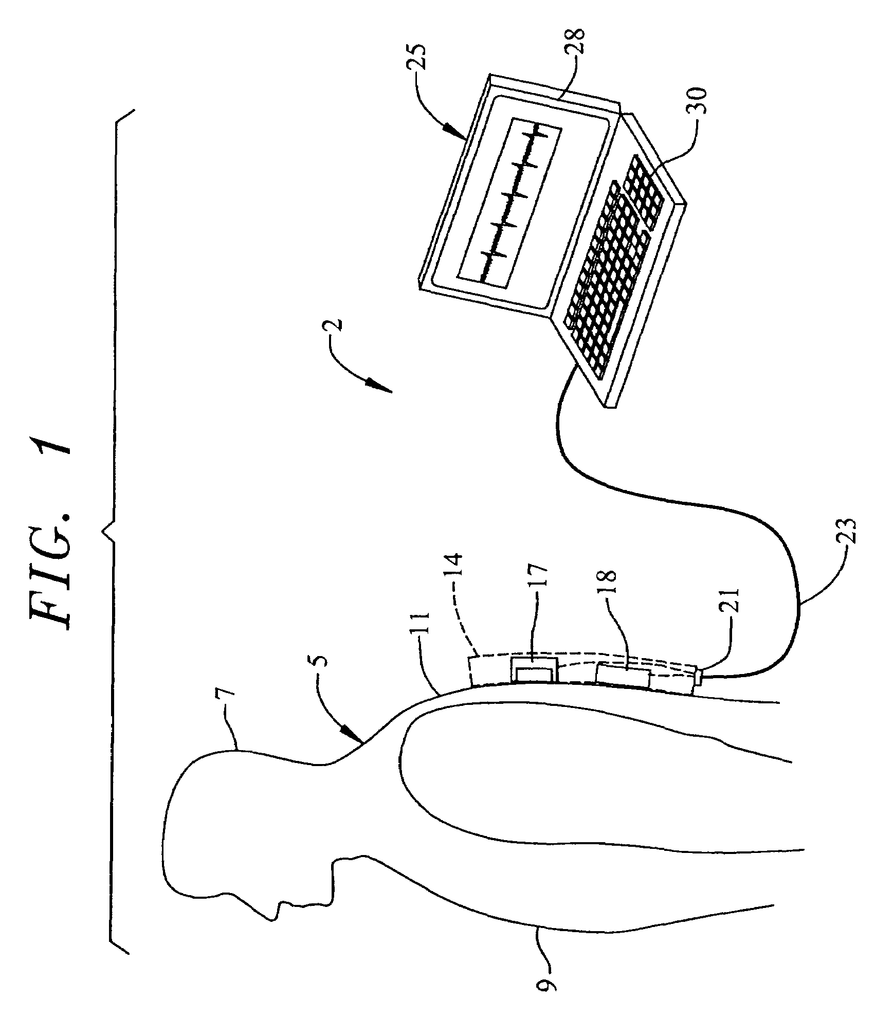
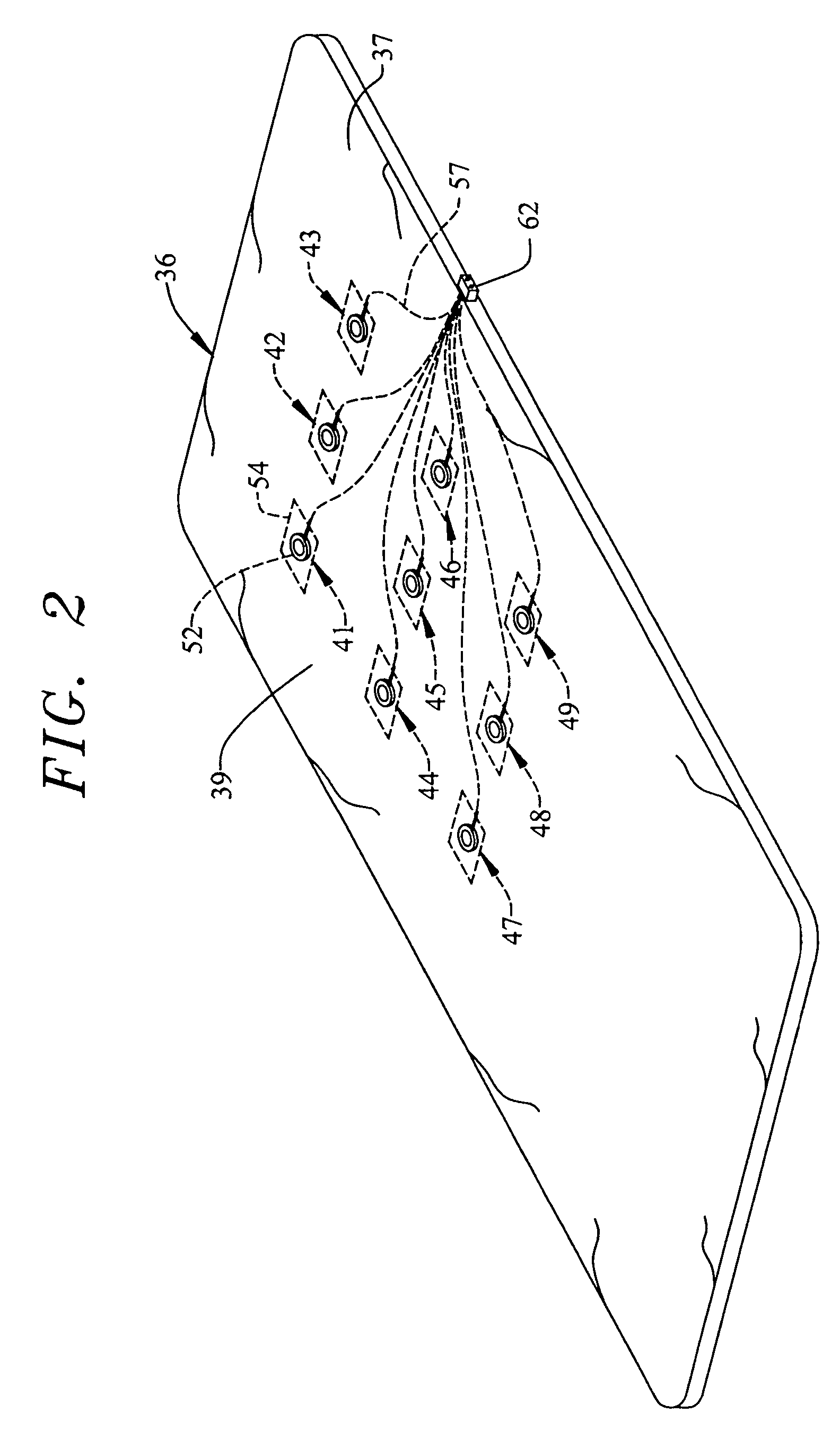
[0017]With initial reference to FIG. 1, a sensor system constructed in accordance with the present invention is generally indicated at 2. In general, sensor system 2 functions to measure biopotentials of an individual 5, such as a medical patient, animal, test subject or the like. As shown, individual 5 includes a head 7, a chest 9 and back 11, with back 11 being positioned against an object which forms part of sensor system 2. In the embodiment shown, the object constitutes a pad 14. More specifically, sensor system 2 includes pad 14 having embedded or otherwise integrated therein at least first and second sensors 17 and 18. In accordance with the invention, at least first sensor 17 constitutes a capacitive-type sensor and, in the most preferred embodiment of the invention, both first and second sensors 17 and 18 constitute capacitive-type sensors.

[0018]As shown, each of first and second sensors 17 and 18 is preferably hardwired to a connector 21 and linked through a cable 23 to a ...


PUM


Abstract

A system for unobtrusively measuring bioelectric signals developed by an individual includes multiple sensors, one or more of which constitutes a capacitive sensor, embedded into or otherwise integrated into an object, such as a chair, bed or the like, used to support the individual. The object serves as mounting structure that holds the sensors in place. The sensors are preferably arranged in the form of an array, with particular ones of the sensors being selectable from the array for measuring the bioelectric signals which are transmitted, such as through a wireless link, for display and / or analysis purposes.

Description

CROSS-REFERENCE TO RELATED APPLICATIONS[0001]The present invention claims the benefit of the filing dates of U.S. Provisional Patent Application Ser. No. 60 / 588,045 filed Jul. 15, 2004 entitled UNOBTRUSIVE MEASUREMENT SYSTEM FOR BIOELECTRIC SIGNALS.BACKGROUND OF THE INVENTION[0002]1. Field of the Invention[0003]The present invention pertains to the art of measuring bioelectric signals and, more particularly, to a system for unobtrusively measuring bioelectric signals developed by an individual.[0004]2. Discussion of the Prior Art[0005]It is widely known that electric fields are developed in free space from many different sources. For example, organs in the human body, including the heart and brain, produce electric fields. For a variety of reasons, it is often desirable to measure these electric fields, such as in performing an electrocardiogram (ECG). Actually, the measuring of bioelectric signals can provide critical information about the physiological status and health of an indi...

Claims


Application Information

Patent Timeline
Patent Type & Authority Patents(United States)
IPC IPC(8): A61B5/0408
CPCA61B5/04085A61B5/0006A61B5/282
Inventor MATTHEWS, ROBERTFRIDMAN, IGORHERVIEUX, PAUL
Owner QUANTUM APPLIED SCI & RES
Learn More