Control device for internal combustion engine

a control device and internal combustion engine technology, applied in the direction of electric control, machines/engines, relays, etc., can solve the problem of engine knocking

Inactive Publication Date: 2007-07-24
NIPPON SOKEN +1
View PDF39 Cites 34 Cited by
  • Summary
  • Abstract
  • Description
  • Claims
  • Application Information

AI Technical Summary

Benefits of technology

[0012]An object of the present invention is to provide an appropriate timing of propagation of a flame in a cylinder to prevent an engine from knocking.
[0013]Another object of the present invention is to reduce smoke, insufficient vaporization of fuel, and insufficient mixture of fuel and air.
[0014]The present invention in one aspect provides a control device for an internal combustion engine including an injector injecting fuel directly into a cylinder. The control device includes: a detector detecting that an engine knocks; and a controller controlling the injector to provide a faster timing of propagation of flame in the cylinder toward an intake side when that the engine knocks is detected.

Problems solved by technology

As a result, the engine tends to knock.

Method used


Image

  • Control device for internal combustion engine
  • Control device for internal combustion engine
  • Control device for internal combustion engine

Examples


first embodiment

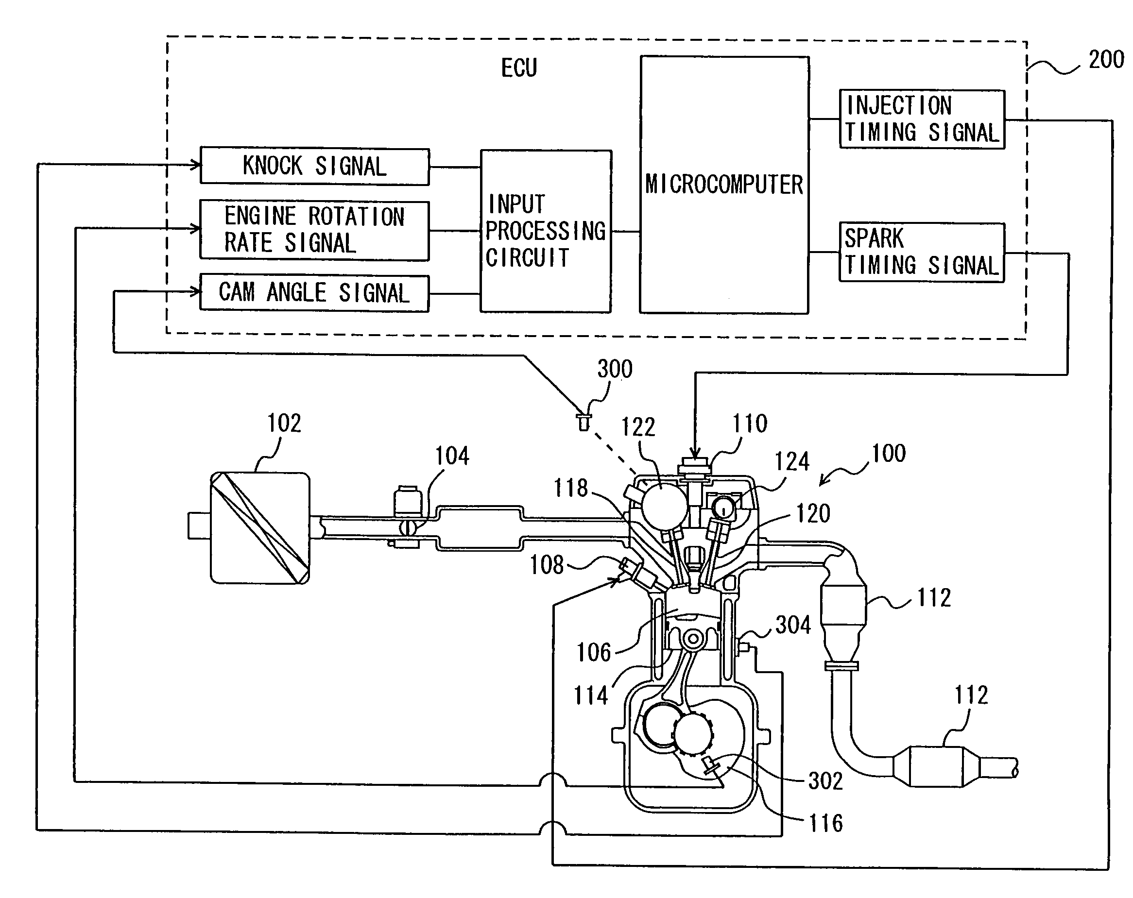
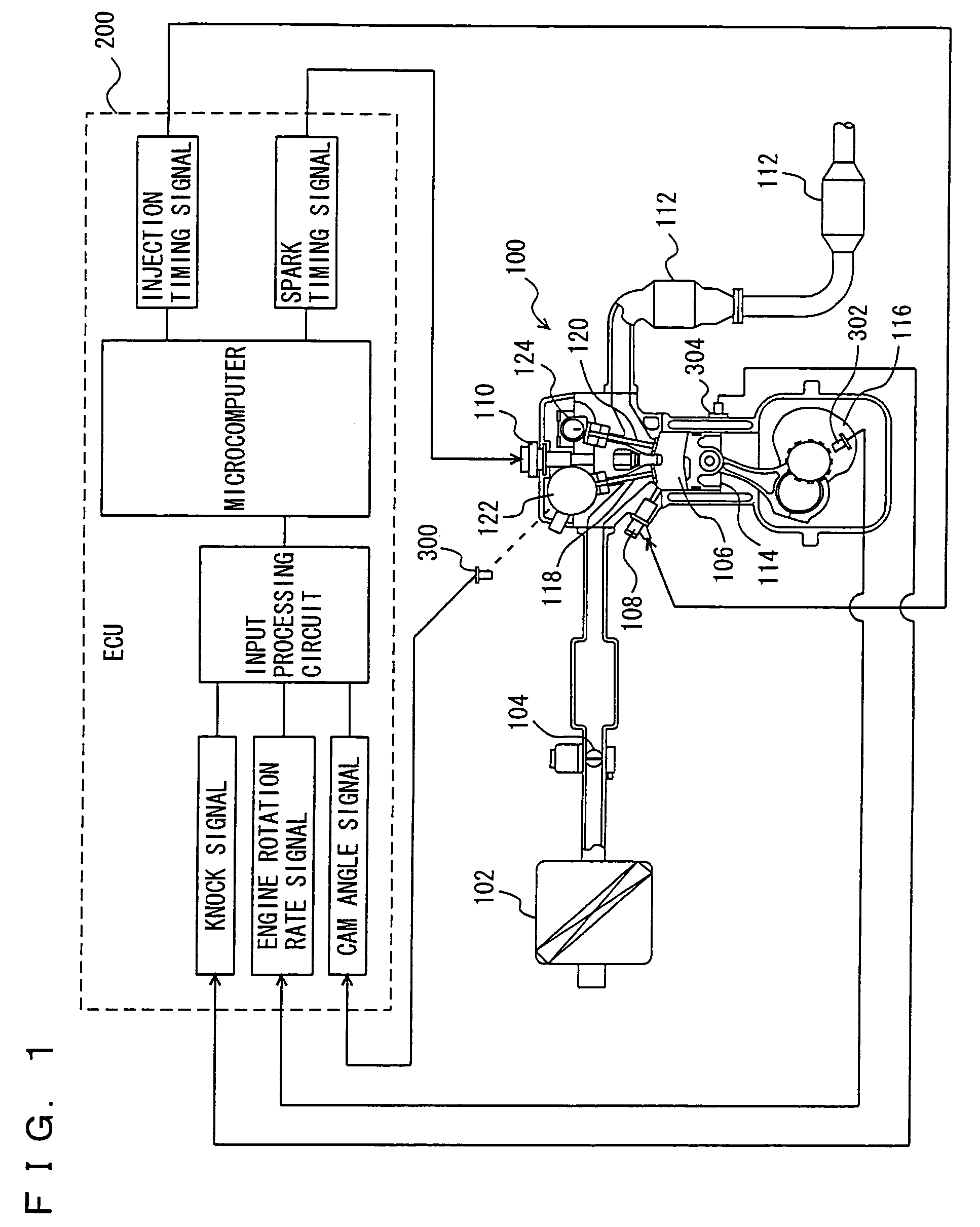
[0075]With reference to FIG. 1 will be described an engine of a vehicle mounting the present control device in a first embodiment. In the present embodiment the control device is implemented for example by a program executed by an electronic control unit (ECU) 200 shown in FIG. 1.

[0076]Engine 100 intakes air from an air cleaner 102 in an amount as adjusted by a throttle valve104 which is a motor driven, electric machinery controlled-throttle valve.

[0077]The air is introduced into a cylinder 106 (a combustion chamber) and mixed with fuel therein. Cylinder 106 receives fuel directly injected thereinto from an injector 108. More specifically, injector 108 has an injection nozzle hole located in cylinder 106. The fuel is injected from that side of cylinder 106 which intakes (or introduces) air.

[0078]The fuel is injected at an intake stroke, although the timing of injection of the fuel is not limited to the intake stroke. Furthermore, while in the present embodiment engine 100 is describ...

second embodiment

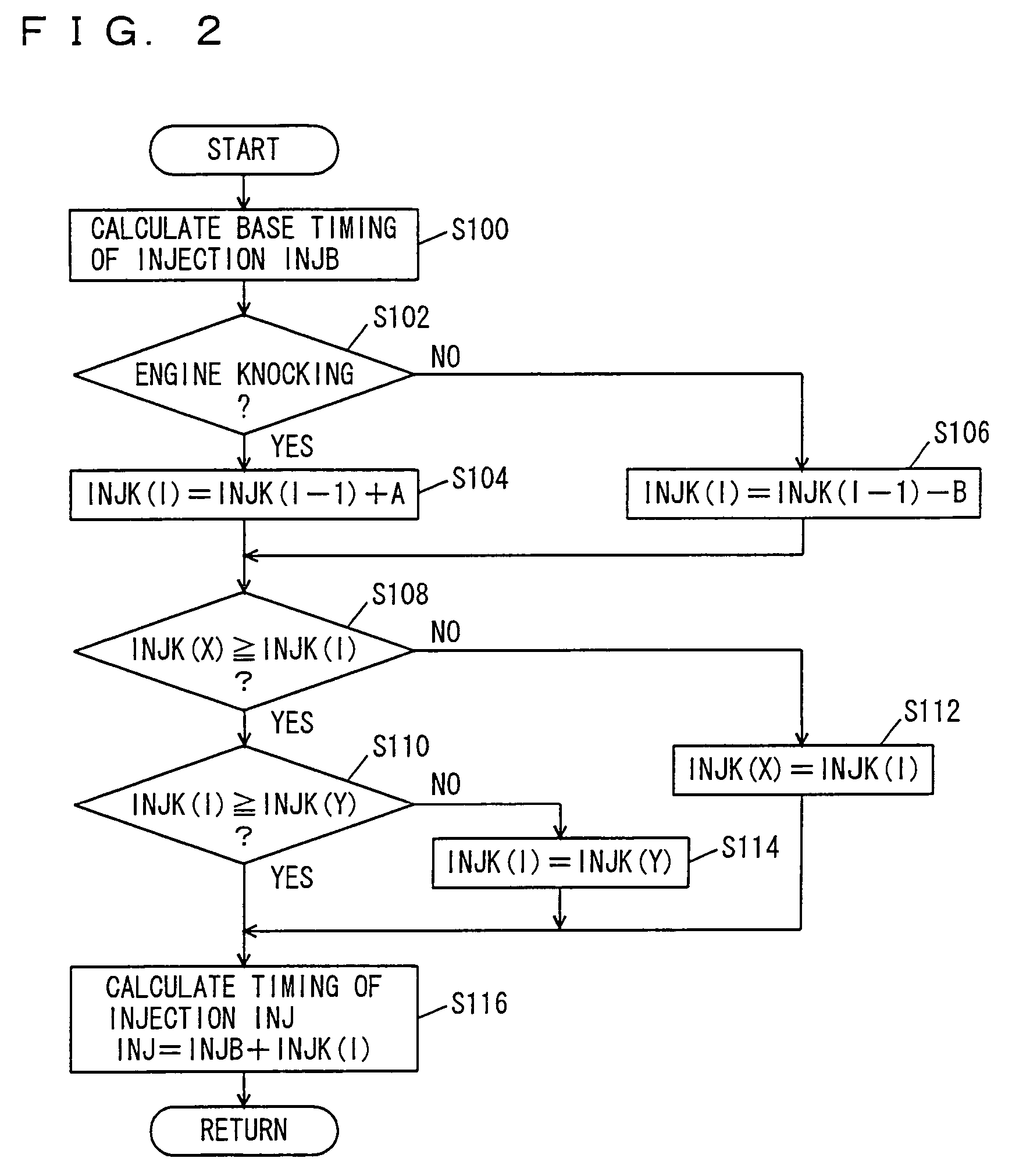
[0105]With reference to FIGS. 7 and 8 the present invention in a second embodiment will be described. In the first embodiment when that an engine knocks is detected a fuel injection advance is introduced at an intake stroke to reduce knocking. In the present embodiment when that an engine knocks is detected and in a cylinder a timing of propagation of flame toward an intake side is slower than that of propagation of flame toward an exhaust side a fuel injection advance is introduced at an intake stroke.

[0106]A timing of propagation of flame in the cylinder is detected by an ion current detection device provided at the cylinder. The remainder is identical in arrangement to that described in the first embodiment and also identical in function.

[0107]With reference to FIG. 7, an engine of a vehicle having mounted therein the present control device in accordance with the present embodiment, will be described. As shown in the figure, cylinder 106 has intake and exhaust sides with their re...

third embodiment

[0121]With reference to FIG. 9 the present invention in a third embodiment will be described.

[0122]In the first and second embodiments a timing of injection of fuel at an intake stroke is corrected to reduce knocking. In the present embodiment a timing of injection and in addition thereto that of spark are corrected. The remainder is identical in arrangement to the first or second embodiment and also identical in function.

[0123]With reference to FIG. 9, ECU 200 implementing the control device in accordance with the present embodiment executes a program for control structured as described hereinafter. The ECU executes the program described in the first or second embodiment and in addition thereto a program as will be described hereinafter.

[0124]At S300 ECU 200 calculates a base timing of spark SAB as based on a map with the engine's rate of rotation, load (torque) and the like serving as parameters. Note that the base timing of spark SAB can be calculated by well-known, general techn...


PUM


Abstract

An ECU executes a program including the steps of: calculating a base timing of injection (INJB); determining whether an engine knocks; if the engine knocks, increasing a correction value INJK(I) applied to correct a timing of injection; and calculating the base timing of injection INJB plus the correction value INJK(I) to obtain a timing of injection INJ.

Description

[0001]This nonprovisional application is based on Japanese Patent Application No. 2004-377397 filed with the Japan Patent Office on Dec. 27, 2004, the entire contents of which are hereby incorporated by reference.BACKGROUND OF THE INVENTION[0002]1. Field of the Invention[0003]The present invention relates generally to control devices for internal combustion engines and particularly to control devices for internal combustion engines having a cylinder receiving fuel directly injected thereinto.[0004]2. Description of the Background Art[0005]Conventionally a direct injection engine directly injecting fuel into a cylinder is commercially available. The direct injection engine includes an engine allowing fuel to be injected at an intake stroke to combust a homogeneous air fuel mixture to provide homogeneous combustion, and an engine allowing fuel to be injected at a compression stroke to combust an air fuel mixture with an air fuel ratio increased around an ignition plug to provide strat...

Claims


Application Information

Patent Timeline
Patent Type & Authority Patents(United States)
IPC IPC(8): F02M7/00H01H47/00
CPCF02D35/027F02D35/028F02D41/3023F02D41/401F02D35/021Y02T10/44Y02T10/40
Inventor NAKASHIMA, TATSUSHIOHTANI, MOTOKI
Owner NIPPON SOKEN
Why Eureka
Try Eureka