Friction roller in conveyor

a friction roller and conveyor technology, applied in the direction of conveyor parts, roller-ways, vehicle components, etc., can solve the problems of increasing or decreasing workability, increasing cost, increasing cost,

Active Publication Date: 2007-07-24
TOYOTA JIDOSHA KK
View PDF13 Cites 2 Cited by
  • Summary
  • Abstract
  • Description
  • Claims
  • Application Information

AI Technical Summary

Benefits of technology

[0014]It is an object of the invention to provide a friction roller in a conveyor, which makes it possible to replace only a worn out elastic ring with a new one so as to suppress an increase in cost.
[0016]According to the first aspect of the invention, in the friction roller, the support roller is formed so as to be divided into two divided portions in the thickness direction, and to be fitted to the elastic ring. That is, the two divided portions of the support roller are inserted into the elastic ring from both sides and are positioned, and then are combined, whereby the friction roller can be assembled. Accordingly, the elastic ring, which wears out when the jig pallet is conveyed in the conveyor, can be removed from the support roller, and replaced with a new one easily. Since only the worn out elastic ring is discarded and a new elastic ring is fitted to the support roller, the support member in the friction roller can be reused, which reduces the cost.
[0018]With this arrangement, since the symmetrical taper faces expanding outward are formed in the inner peripheral face of the elastic ring, one of the two divided portions of the support roller is inserted from one side such that a taper face formed in an outer peripheral face of the one divided portion is engaged with the taper face of the elastic ring, whereby the divided portion is positioned with respect to the elastic ring, and is internally fitted to the elastic ring. Then, the other divided portion is inserted from the side opposite to the one divided portion, and is internally fitted to the elastic ring and positioned such that a taper face formed in an outer peripheral face of the other divided portion is engaged with the taper face of the elastic ring. Thus, the friction roller can be assembled, and the divided portions can be removed easily. Also, since each of the divided portions can be positioned by engaging the taper face thereof with the taper face of the elastic ring, the friction roller can be assembled also in the thickness direction with high accuracy.
[0020]With this arrangement, since the inclination angle of the taper face formed in the outer peripheral face of each of the divided portions is smaller than that of each of the taper faces formed in the inner peripheral face of the elastic ring, the divided portions can be fitted to the elastic body and can be removed from the elastic body easily. Also, when both the divided portions are fitted to the elastic ring, the elastic ring is compressed in the thickness direction, whereby each of the taper faces formed in the inner peripheral face of the elastic ring can be pressed against, and engaged with the taper face formed in the outer peripheral face of each of the both divided portions. Also, the elastic ring can be tightly clamped by the two divided portions of the support roller.
[0022]With this arrangement, since the knurling portion is formed in the taper face of each of the two divided portions, the divided portions of the support roller and the elastic ring come into contact with each other via the knurling portion, which increases the frictional resistance. Therefore, slipping is unlikely to occur, and efficiency of transmitting the rotation from the support roller to the elastic ring can be improved.
[0024]In the case where the friction roller is fitted to the conveyor and is used for a long time, when a wear amount of the elastic ring reaches a predetermined amount, the elastic ring is replaced with a new one. With the aforementioned arrangement, a reference for determining a time at which the elastic ring needs to be replaced with a new one is indicated by the concave groove or the protrusion ring formed in the one lateral face of the elastic ring, as a slip sign. Therefore, the time at which the elastic ring needs to be replaced with a new one can be visibly determined easily. Thus, the elastic ring can be replaced with a new one at an appropriate time.

Problems solved by technology

As a result, cost increases or workability decreases.
In other words, as described above, since peeling the joined elastic plate from the cylindrical body results in a decrease in workability, the external cylinder itself needs to be replaced with a new one, which increases the cost.
Also, when the external cylinder is externally fitted to the roller main body, the external cylinder needs to be prevented from dropping off the roller main body using an engagement ring, which results in an increase in cost and a decrease in workability.
Accordingly, it is not suitable to use the roller as the friction roller for a conveyor for conveying, for example, an automobile body which applies a large load, since the roller would greatly wear out due to the large load.
Therefore, when the elastic member wears out, the elastic member needs to be discarded together with the metallic fitting member, which results in an increase in cost.

Method used


Image

  • Friction roller in conveyor
  • Friction roller in conveyor
  • Friction roller in conveyor

Examples


Embodiment Construction

[0039]Hereinafter, an embodiment of the invention will be described with reference to the accompanying drawings.

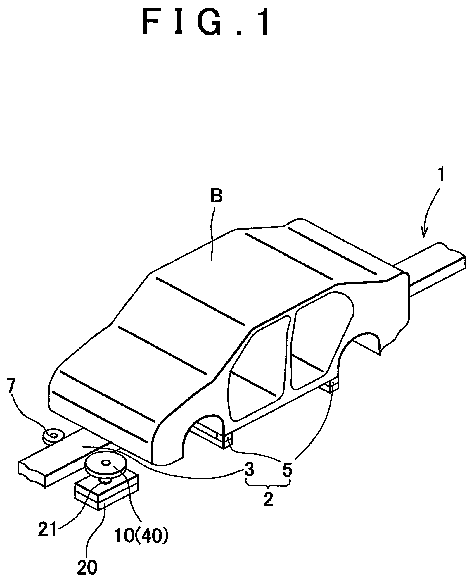
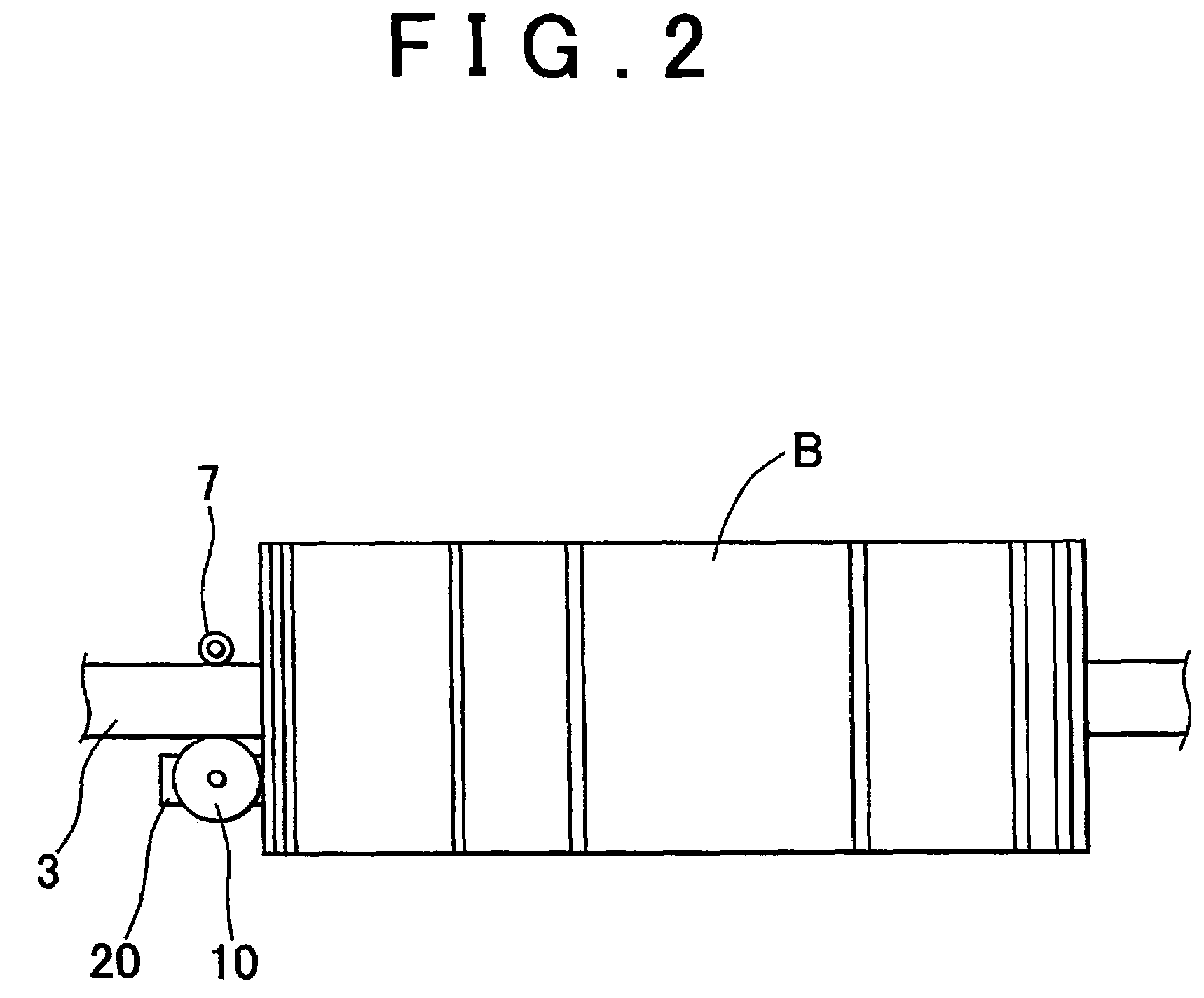
[0040]A friction roller according to the embodiment of the invention is suitably used in a part of a conveyor which conveys an upper automobile body to a welding process in an automobile body assembly line. As shown in FIG. 1 to FIG. 3, a jig pallet 2 on which an automobile body B is placed in a conveyor 1 includes a rail 3 which is formed to be long, and a pair of horizontal members 5 which is fitted on the rail 3, and which is arranged in parallel in a direction orthogonal to a longitudinal direction of the rail 3. The automobile body B is placed on the pair of horizontal members 5. The rail 3 has a cross section having a rectangular shape. The rail 3 can be moved in the longitudinal direction of the rail 3.

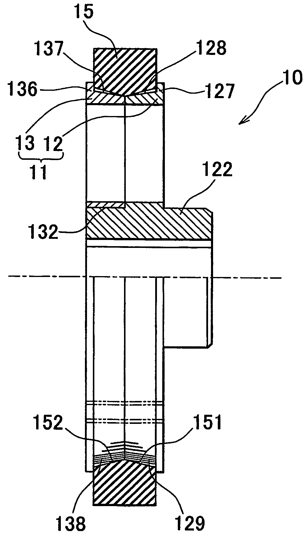
[0041]A pair of frames (not shown) is disposed with the rail 3 being therebetween. A friction roller 10 which can be pressed against a lateral face of the rail 3 is f...


PUM


Abstract

A friction roller (10) includes a support roller (11) and an annular elastic ring (15) which it externally fitted to the support roller (11). The support roller (11) is divided into two portions in a thickness direction, that is, a first divided roller (12) and a second divided roller (13). A flange (127) is formed on one side of the first divided roller (12), and a taper face (128) is formed in an outer peripheral face of the first divided roller (12). A knurling portion (129) is formed in the taper face (128). A flange (136) is formed on one side of the second divided roller (13), and a taper face (137) is formed in an outer peripheral face of the second divided roller (13). A knurling portion (138) is formed in the taper face (137). Meanwhile, taper faces (151, 152) expanding outward are formed in an inner peripheral face of the elastic ring (15). The taper faces (151, 152) of the elastic ring (15) are engaged with the taper face (128) of the first divided roller (12) and the taper face (137) of the second divided roller (13).

Description

BACKGROUND OF THE INVENTION[0001]1. Field of the Invention[0002]The invention relates to a friction roller in a conveyor. More particularly, the invention relates to a friction roller in a conveyor which conveys an object in an assembly line.[0003]2. Description of the Related Art[0004]Japanese Patent Laid-Open Publication No. JP-A-8-207843 discloses an example of a conveyor which conveys an upper automobile body to a welding process in an automobile body assembly line. In this case, a conveyor 31 includes a long frame 32, and multiple friction rollers 33 fitted to a lateral portion of the frame 32 in a longitudinal direction, as shown in FIG. 13. Each of the friction rollers 33 is driven to rotate when a rotation shaft 35 is rotated by a gear mechanism 36 connected to a drive shaft of a motor 34. A jig pallet 37 on which an upper automobile body B is placed is conveyed on the friction rollers 33. According to the Japanese Patent Laid-Open Publication No. JP-A-8-207843, the assembly...

Claims


Application Information

Patent Timeline
Patent Type & Authority Patents(United States)
IPC IPC(8): B65G39/02B65G39/10
CPCB65G39/02Y10T152/10405B65G2201/0267
Inventor YAMAHARA, YASUSHIMOTODA, MASANORIKIMURA, MASASHISUGIURA, MASAHARUISHII, AKIRAAOKI, TOSHITAKA
Owner TOYOTA JIDOSHA KK
Why Eureka
Try Eureka