Carbon fiber heating element assembly and methods for making

a technology of heating element and carbon fiber, which is applied in the direction of fluid heater, heating type, lighting and heating apparatus, etc., can solve the problem that the potential for such use has not yet been fully realized

Active Publication Date: 2007-07-24
METHODE ELETRONICS INC
View PDF12 Cites 22 Cited by
  • Summary
  • Abstract
  • Description
  • Claims
  • Application Information

AI Technical Summary

Benefits of technology

[0007]In accordance with the present invention, a heating element assembly comprises an axially elongated longitudinally extending generally flat bundle of substantially rectilinear continuous carbon fibers or filaments of indeterminate axial length. The bundle has a predetermined electrical resistance per unit of axial length and is disposed between generally flat layers of dielectric sheet material arranged in opposing face-to-face relation to each other with one of the layers in direct overlying contacting engagement with and unconnected relation to an associated flat surface of the bundle and the other of the layers adhered to another flat surface of the bundle opposite the associated flat surface. Marginal portions of the layers are connected to each other along the entire axial length of the bundle and immediately adjacent longitudinally extending transversely opposite sides of the bundle, whereby a sheath formed by the layers is sealed against axially transverse migration of moisture through the sheath. The sheath also serves to electrically insulate the bundle.

Problems solved by technology

Advantages in the use of carbon in the electrical field were early recognized by pioneers in that field, and although artificially produced carbon fiber has found some limited usage in electrically operated heating device, the potential for such usage has not yet been fully realized.

Method used


Image

  • Carbon fiber heating element assembly and methods for making
  • Carbon fiber heating element assembly and methods for making
  • Carbon fiber heating element assembly and methods for making

Examples


Embodiment Construction

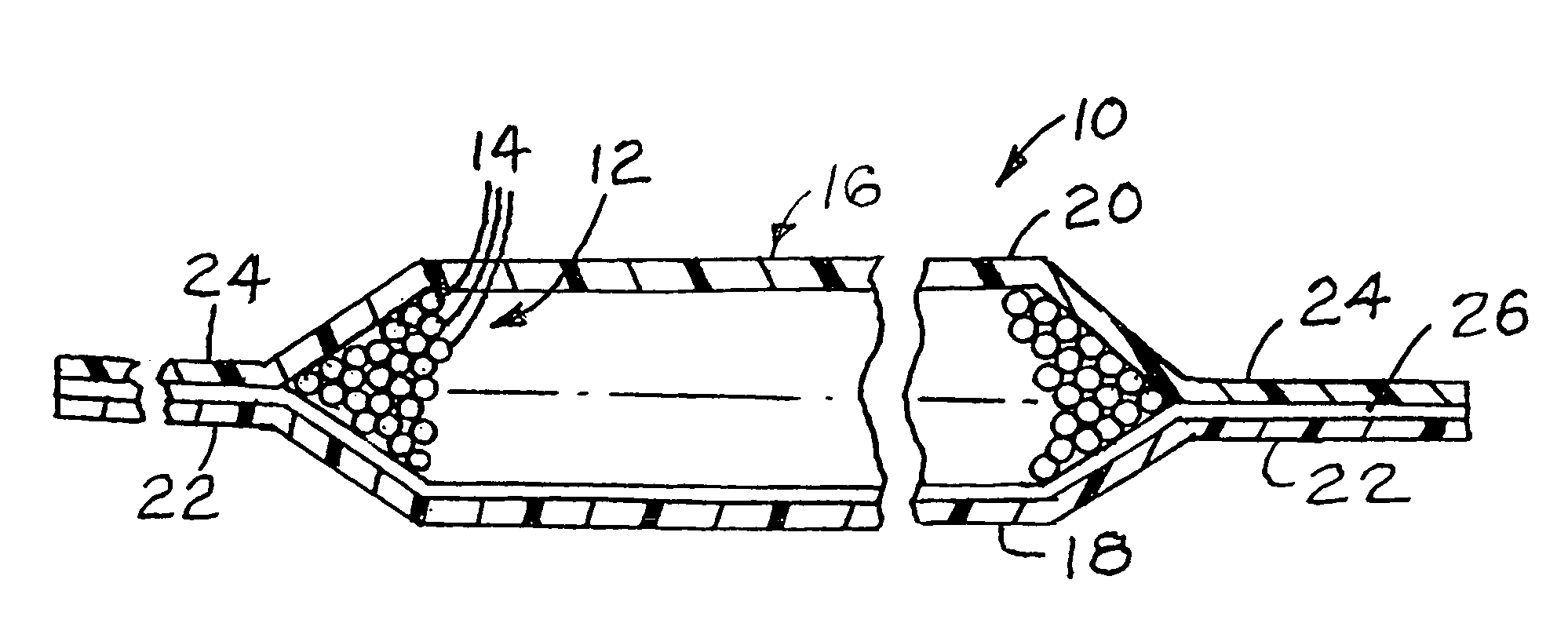
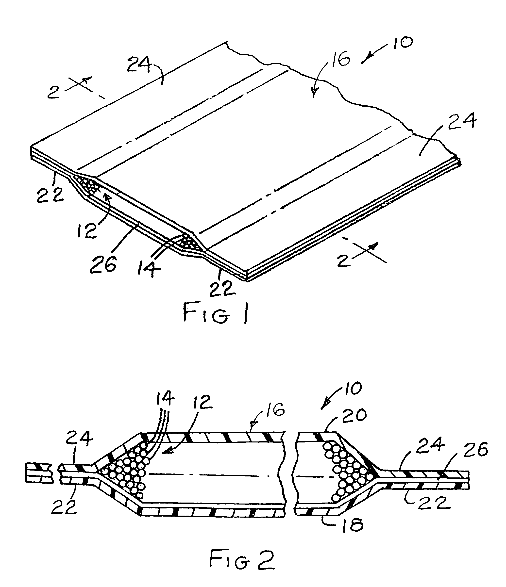
[0020]Turning now to the drawings and referring first particularly to FIGS. 1 and 2, a typical heating element assembly embodying the present invention and made in accordance with the invention is indicated generally by the reference numeral 10. In the description which follows and in the claims directional terms such as upper and lower are employed for convenience and refer to the illustrated heating element assembly 10 as oriented in the drawings, however, it should be understood that the heating element assembly of the present invention may be operated in any orientation.

[0021]The illustrated heating element assembly 10 essentially comprises an axially elongated substantially flat bundle of individual continuous carbon fibers or filaments, which cooperate to form an electrical heating element which transforms electrical energy applied thereto into heat energy, the flat bundle or heating element being designated generally by the reference numeral 12 and that individual fibers or f...


PUM


Abstract

An electrical resistance heating element has an axially elongated flat carbon fiber tow, which includes a multiplicity of continuous axially parallel carbon filaments. The tow is sandwiched between two layers of polyester sheet material and bonded to only one of the layers. The other of the layers overlies the tow in direct contacting engagement with and unconnected relation to the tow and is connected to longitudinally extending marginal portions of the one layer along transversely opposite sides of the tow. The heating element may be produced by a continuous forming process.

Description

FIELD OF THE INVENTION[0001]This invention relates in general to heating element assemblies and deals more particularly with improvements in non-metallic heating element assemblies of electrical resistance type.BACKGROUND OF THE INVENTION[0002]The present invention is particularly concerned with improvements in non-metallic heating element assemblies and particularly electrically conductive carbon fiber heating element assemblies suitable for general purpose usage in a wide variety of heating applications.[0003]The development of improved processes for artificially producing staple carbon in fibrous or filamentary form and at reasonable cost has virtually revolutionized the plastic composite industry, particularly where light weight and a high degree of mechanical integrity is desired. New materials embodying carbon in fibrous or filamentary form now enjoy wide spread use in the production of golf shafts, aircraft parts, and indeed entire airframes, to cite a few outstanding example...

Claims


Application Information

Patent Timeline
Patent Type & Authority Patents(United States)
IPC IPC(8): H05B3/34H05B3/02H05B3/14
CPCH05B3/145
Inventor JOHNSTON, JAMES J.
Owner METHODE ELETRONICS INC
Why Eureka
Try Eureka