PWM power supplies using controlled feedback timing and methods of operating same

a technology of power supply and feedback timing, applied in the direction of emergency power supply arrangement, switch power arrangement, instruments, etc., can solve the problem that the loop lacks sufficient phase margin to remain stable, and achieve the effect of improving phase margin and high modulation ra

Active Publication Date: 2007-07-24
EATON INTELLIGENT POWER LIMITED
View PDF27 Cites 10 Cited by
  • Summary
  • Abstract
  • Description
  • Claims
  • Application Information

AI Technical Summary

Benefits of technology

[0010]Power supply apparatus and methods according to the invention can provide several advantages over conventional apparatus and methods. In particular, using different rates for feedback filtering and compensation in a power converter loop according to the invention can provide improved phase margin and, therefore, stability, without requiring the use of analog control networks and / or high modulation rates.

Problems solved by technology

A potential problem with such an output filter is that it may introduce a complex pole in the transfer function of the loop circuit at a frequency that can degrade function of the loop.
In particular, such a complex pole can provide sufficient additional phase lag at the unity gain crossover point of the loop such that the loop lacks sufficient phase margin to remain stable in response to step changes in the loading of the UPS or in response to the presence of non-linear loads.

Method used


Image

  • PWM power supplies using controlled feedback timing and methods of operating same
  • PWM power supplies using controlled feedback timing and methods of operating same
  • PWM power supplies using controlled feedback timing and methods of operating same

Examples


Embodiment Construction

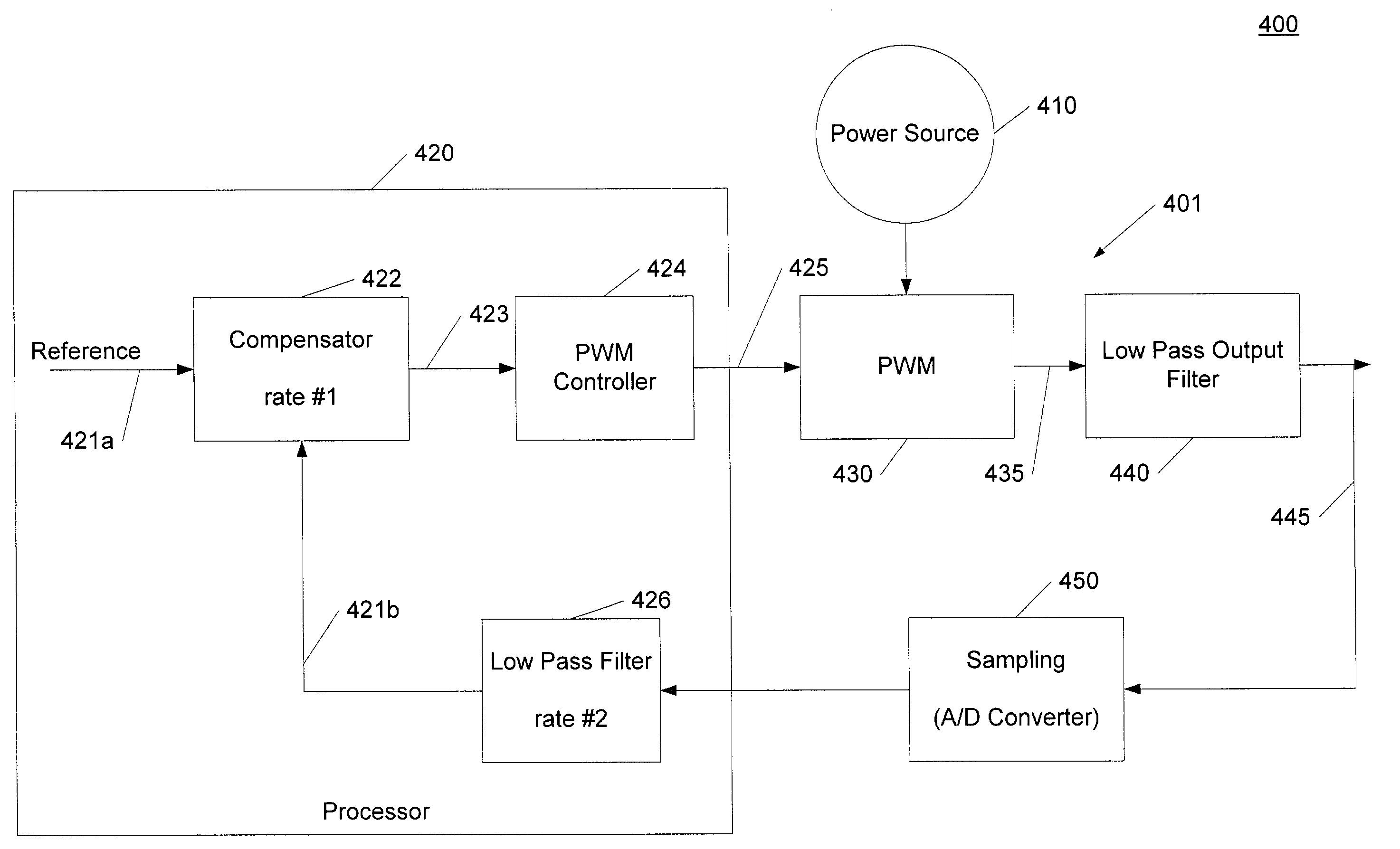
[0020]The present invention will now be described more fully with reference to the accompanying drawings, in which exemplary embodiments of the invention are shown. These embodiments are provided so that this application will be thorough and complete. In the drawings, like numbers refer to like elements. It will be understood that when an element is referred to as being “connected” or “coupled” to another element, it can be directly connected or coupled to the other element or intervening elements may be present. In contrast, when an element is referred to as being “directly connected” or “directly coupled” to another element, there are no intervening elements present.

[0021]As discussed above, analog techniques have conventionally been used to compensate for undesirable phase lag associated with a low pass output filter in a power supply, such as a UPS. Translating these techniques to a digital control domain may be problematic.

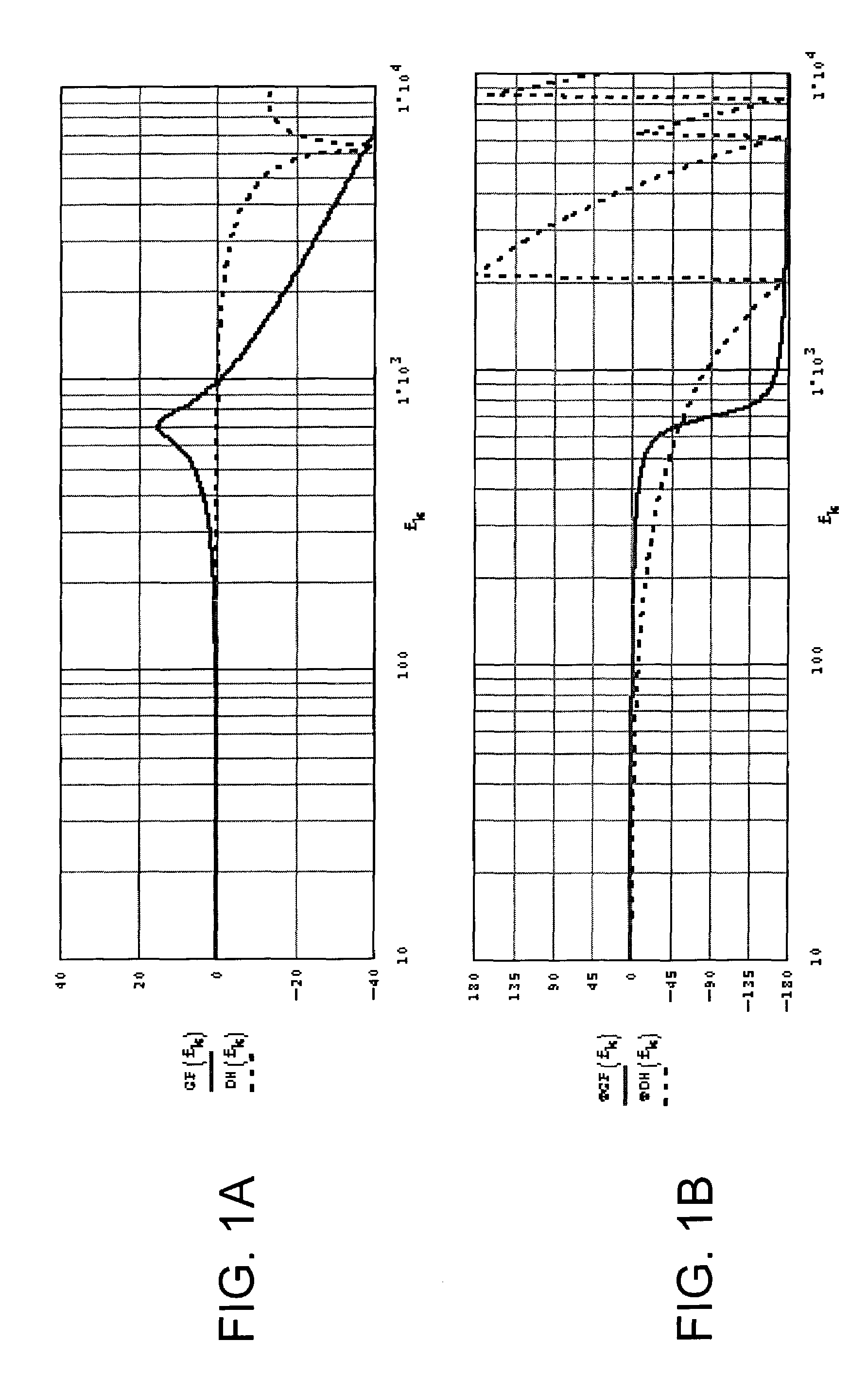
[0022]Referring to FIGS. 1A and 1B, bold lines illustra...


PUM


Abstract

A closed loop power converter circuit of a UPS or other power supply includes a pulse width modulator circuit in a forward path of the closed loop power circuit. A compensation circuit provides pulse width commands to the pulse width modulator at a first rate. A feedback circuit digitally filters samples of an output of the closed loop power converter at a second rate greater the first rate and that provides the filtered samples to the compensation circuit. In some embodiments, the compensation circuit may be operative to compensate for the phase lag associated with a low pass output filter.

Description

BACKGROUND OF THE INVENTION[0001]The present invention relates to power conversion apparatus and methods, and more particularly, to power supply apparatus and methods of operating the same.[0002]Traditionally, uninterruptible power supplies (UPSs) largely used analog control techniques to control power conversion circuitry, such as pulse width modulators (PWMs). However, recent years have brought increased use of digital control techniques in UPSs, typically implemented in a microprocessor, microcontroller or digital signal processor (DSP).[0003]A typical UPS may include a closed loop PWM circuit that includes a PWM that generates an AC output voltage from a DC source, e.g., a battery and / or rectifier output. A low pass filter is typically included in the loop at the output of the PWM circuit. The low pass filter may be used to filter out unwanted high frequency components generated by the operation of the PWM and thereby provide a smoothed AC output voltage waveform.[0004]A potenti...

Claims


Application Information

Patent Timeline
Patent Type & Authority Patents(United States)
IPC IPC(8): H01H3/26H02J9/06
CPCH02J9/062
Inventor TRACY, JOHN G.TASSITINO, JR., FREDERICKPFITZER, HANSBOBB, RENNIERICE, JULIUS
Owner EATON INTELLIGENT POWER LIMITED
Why Eureka
Try Eureka