Process and temperature-compensated transimpedance amplifier

a transimpedance amplifier and temperature compensation technology, applied in the field of electromechanical devices, can solve the problems of reducing the performance of transimpedance amplifiers, too much noise is introduced into the output signal of transimpedance amplifiers, and too high transimpedance gain, so as to achieve constant output and improve phase margin

Inactive Publication Date: 2006-03-30
DEMONT & BREYER
View PDF2 Cites 15 Cited by
  • Summary
  • Abstract
  • Description
  • Claims
  • Application Information

AI Technical Summary

Benefits of technology

[0012] The present invention enables an optical receiver that avoids some of the costs and disadvantages found in the prior art. In particular, the illustrative embodiment comprises a transimpedance that exhibits an improved phase margin and substantially constant output in response to changes in operating conditions (e.g., temperature, process, etc.).
[0013] In accordance with the illustrative embodiment, a common-mode feedback comparison is performed prior to conversion of the signal from single-ended to differential voltage. When the common-mode feedback comparison is performed in this way, there are fewer amplifiers in the signal path and the phase margin of the common-mode feedback loop is increased. In addition, as the common-mode feedback is performed at the first stage of the transimpedance amplifier, the gain response of the transimpedance amplifier remains substantially constant in response to changes in temperature, input current range, and for different integrated circuit fabrication processes.

Problems solved by technology

This common-mode voltage causes a voltage offset of the signal that degrades the performance of transimpedance amplifier 102.
However, too much noise is introduced into the output signal of transimpedance amplifier 102 if transimpedance stage 204 has a transimpedance gain that is too high.
It is often difficult build a transimpedance amplifier with a lot of gain, but low phase shift, and, therefore, a trade-off exists between gain and phase shift.
Furthermore, it is challenging to suppress the voltage offset caused by the common-mode voltage without inducing phase shift.

Method used


Image

  • Process and temperature-compensated transimpedance amplifier
  • Process and temperature-compensated transimpedance amplifier
  • Process and temperature-compensated transimpedance amplifier

Examples


Embodiment Construction

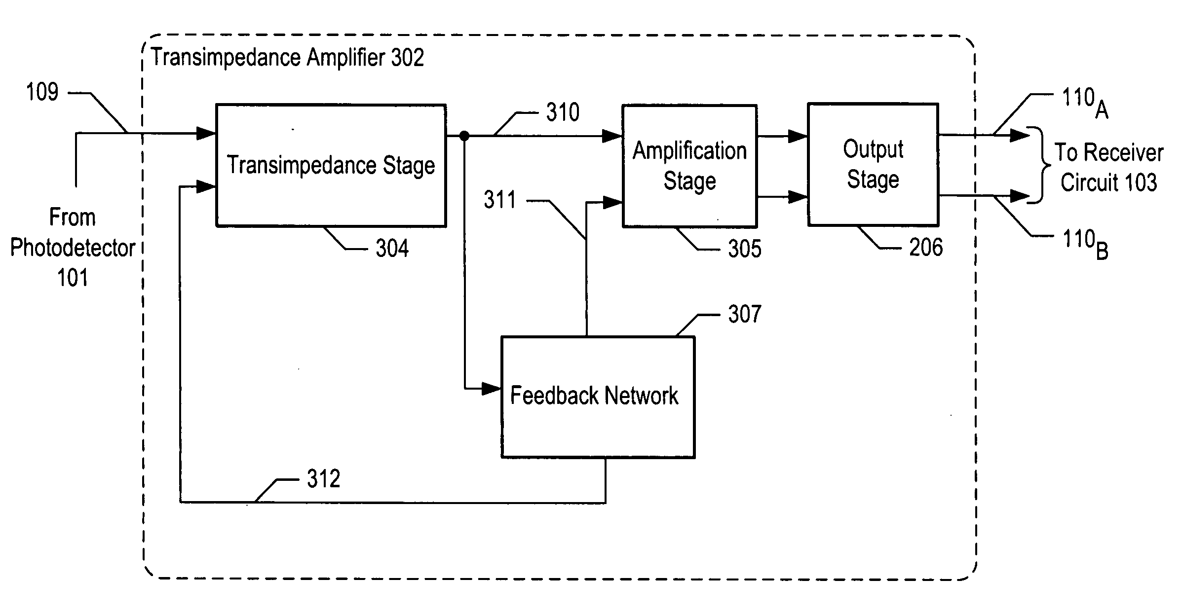
[0021]FIG. 3 depicts a schematic diagram of the salient components of transimpedance amplifier 302 in accordance with the illustrative embodiment of the present invention. In accordance with the illustrative embodiment, transimpedance amplifier 302 exhibits a gain of 104 dBΩ. It will be clear to those skilled in the art, however, after reading this specification, how to make and use embodiments of the present invention that have a different gain.

[0022] Transimpedance amplifier 302 comprises: transimpedance stage 304 (comprising signal input 109, bias input 312, and output 310, amplification stage 305, output stage 206, and feedback network 307, interconnected as shown.

[0023] Transimpedance stage 304 converts a current at its signal input into a single-ended voltage signal at its output. In accordance with the illustrative embodiment, transimpedance stage 304 has a transimpedance gain of 60 dBΩ. The details of transimpedance stage 304 are described in detail below and with respect ...


PUM


Abstract

An optical receiver is disclosed that exhibits an improved phase margin and substantially constant output in response to changes in operating conditions (e.g., temperature, process, etc.). In accordance with the illustrative embodiment, a common-mode feedback comparison is performed prior to conversion of the signal from single-ended to differential voltage. When the common-mode feedback comparison is performed in this way, there are fewer amplifiers in the signal path and the phase margin of the common-mode feedback loop is increased. In addition, as the common-mode feedback is performed at the first stage of the transimpedance amplifier, the gain response of the transimpedance amplifier remains substantially constant in response to changes in temperature, input current range, and for different integrated circuit fabrication processes.

Description

REFERENCE TO RELATED APPLICATIONS [0001] This application claims the benefit of U.S. Provisional 60 / 613,370, filed Sep. 27, 2004, which is also incorporated by reference.FIELD OF THE INVENTION [0002] The present invention relates to electronics in general, and, more particularly, to transimpedance amplifiers. BACKGROUND OF THE INVENTION [0003]FIG. 1 depicts the salient components of an optical telecommunications system in the prior art. The system comprises: optical fiber 110 and optical receiver 100, which itself comprises: photodetector 101, transimpedance amplifier 102, and receiver circuit 103. Optical fiber 110 is used to carry optical signals, and optical receivers are used in optical communications systems to detect and convert optical signals into electrical signals that can be processed by electronic systems or converted into sound. [0004] Photodetector 101 is a device that receives light from optical fiber 110 and outputs an electrical current that is based on the intensit...

Claims


Application Information

Patent Timeline
Patent Type & Authority Applications(United States)
IPC IPC(8): H04B10/06
CPCH03F1/08H03F1/30H04B10/6933H03F2200/447H03F3/08
Inventor FAROOQUI, ARSHAD SUHAILYING, LEE WEN
Owner DEMONT & BREYER
Why Eureka
Try Eureka