Signal processing method for use with an optical navigation system

a technology of optical navigation and signal processing, applied in the field of signal processing, can solve the problems of limiting the usefulness of the technique in power sensitive applications, unsatisfactory power consumption, and affecting the use of speckle-based devices,

Active Publication Date: 2007-07-24
CYPRESS SEMICON CORP
View PDF56 Cites 31 Cited by
  • Summary
  • Abstract
  • Description
  • Claims
  • Application Information

AI Technical Summary

Problems solved by technology

In either case, the correlation used to track the motion of the image requires a great deal of processing and results in an unsatisfactory power consumption that limits the usefulness of the technique in power sensitive applications, such as wireless mice.
Although a significant improvement over prior art, these speckle-based devices have not been wholly satisfactory for a number of reasons.
In particular, optical navigation systems using the above 1D comb-array have not demonstrated the accuracy demanded in state-of-the-art pointing devices today, which generally must have a path error of less than 0.5%.
Furthermore, the above approach involves processing signals from multiple signal processing paths, and suffers from relatively complex signal processing requirements.
Another problem with the above speckle-based devices is their limited accuracy along directions that deviate significantly from orientations the 1D array.
This is especially a problem where the optical mouse is moved in an off-axis direction causing the speckle pattern or image to enter and leave the field of view of the 1D array too quickly before the image has a chance to build-up an unambiguous signal.
This deficiency can be partially remedied by increasing the number of axes, but at the price of reducing the simplicity of the linear comb-array approach.

Method used


Image

  • Signal processing method for use with an optical navigation system
  • Signal processing method for use with an optical navigation system
  • Signal processing method for use with an optical navigation system

Examples


Embodiment Construction

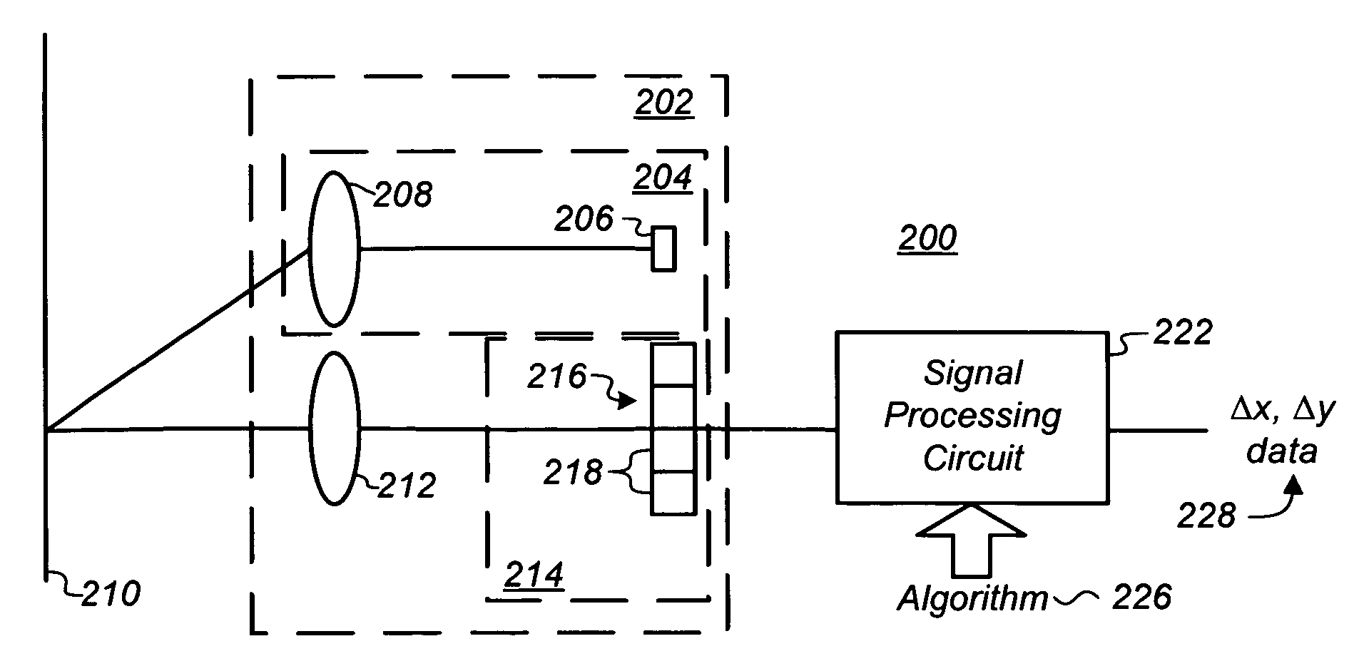
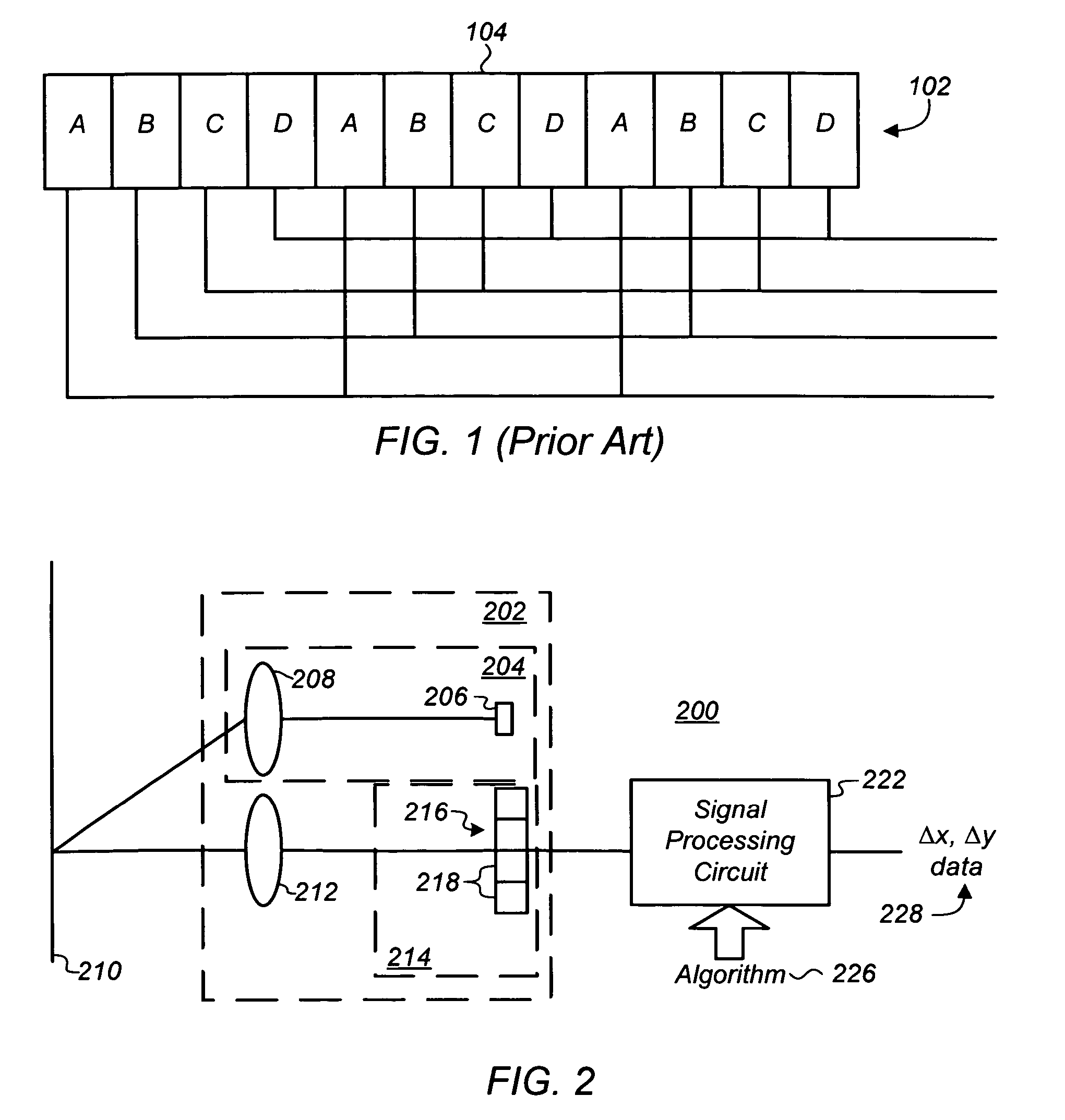
[0020]The present invention is directed to signal processors or signal processing circuits and methods, and more particularly for use in optical navigation systems with comb detector arrays to determine motion of the system relative to a surface without the use of sinusoidal signals.

[0021]Optical navigation systems can include, for example, an optical computer mouse, trackballs and the like, and are well known for inputting data into and interfacing with personal computers and workstations. For purposes of clarity, many of the details of optical navigation systems in general and optical sensors for optical navigation systems in particular that are widely known and are not relevant to the present invention have been omitted from the following description. Optical navigation systems and optical sensors are described, for example, in co-pending, commonly assigned U.S. patent application Ser. No. 11 / 129,967, entitled, “Optical Positioning Device Having Shaped Illumination,” filed on May...


PUM


Abstract

A signal processor and method are provided for detecting movement of a surface relative to an optical sensor having an array of photosensitive elements. Generally, the method involves: (i) sampling each of a number (M) of phase signals from the photosensitive elements, each of the M signals having a magnitude (Ai) and including a tracking signal at a frequency being tracked and a background signal at other frequencies that offsets the tracking signal, where i, an index of the signals, is a whole number between 0 and M-1; (ii) eliminating the offset to the tracking signal due to the background signal to generate M non-offset phase signals having a magnitude (A′i); (iii) adjusting phase angles (θi) of the non-offset phase signals to generate M weighted phase signals (A′iθ′i); and (iv) combining each of the M weighted phase signals (A′iθ′i) to generate an average weighted phase having a phase angle (θ), that when tracked over time indicates a direction and velocity of the movement of an image of the surface mapped to the array.

Description

CROSS-REFERENCE TO RELATED APPLICATIONS[0001]The present application claims the benefit of priority under 35 U.S.C. 119(e) to U.S. Provisional Patent Application Ser. No. 60 / 627,225, filed on Nov. 12, 2004 entitled A Method for Determining Motion Without Sinusoidal Signals; which application is hereby incorporated by reference.TECHNICAL FIELD[0002]The present invention relates generally to signal processing, and more particularly to a signal processing circuit and method for use with an optical navigation system for determining movement of an optical sensor relative to a surface without the use of sinusoidal signals.BACKGROUND OF THE INVENTION[0003]Signal processors are used in a wide range of applications including, for example, measuring a current output from a photo-detector of an array in an optical navigation system. Optical navigation systems, such as an optical computer mouse or trackball, are well known for inputting data into and interfacing with personal computers and work...

Claims


Application Information

Patent Timeline
Patent Type & Authority Patents(United States)
IPC IPC(8): G01P3/36G09G5/08
CPCG06F3/0317
Inventor TODOROFF, BRIAN D.XU, YANSUN
Owner CYPRESS SEMICON CORP
Why Eureka
Try Eureka