Perpendicular magnetic recording head and method for manufacturing the same

a technology of perpendicular magnetic and recording heads, which is applied in the direction of head surfaces, head surfaces with metal sheet cores, instruments, etc., can solve the problems of affecting the quality of the recording medium, the spread of magnetic flux passing from the main magnetic pole layer to the return path layer m cannot be effectively reduced, and the substantial recording track width is liable to increase. , to achieve the effect of easy control of the substantial recording track width

Active Publication Date: 2007-07-24
TDK CORPARATION
View PDF16 Cites 33 Cited by
  • Summary
  • Abstract
  • Description
  • Claims
  • Application Information

AI Technical Summary

Benefits of technology

[0019]Accordingly, the present invention was made to solve the problem described above, and an object of the present invention is to provide a perpendicular magnetic recording head and a method for manufacturing the same, in the perpendicular magnetic recording head of the present invention, a magnetic field generated therefrom can be effectively converged and a substantial recording track width can be easily controlled in a predetermined range.

Problems solved by technology

However, when the intensity of the magnetic field is simply enhanced as described above, the spread of the magnetic flux passing from the main magnetic pole layer to the return path layer 2 through the recording medium M cannot be effectively reduced.
In particular, when the intensity of the magnetic field is simply enhanced, the magnetic field generated from the main magnetic pole layer is spread in the track width direction (X direction in the figure), and a problem may arise in that a substantial recording track width is liable to increase.

Method used


Image

  • Perpendicular magnetic recording head and method for manufacturing the same
  • Perpendicular magnetic recording head and method for manufacturing the same
  • Perpendicular magnetic recording head and method for manufacturing the same

Examples


first embodiment

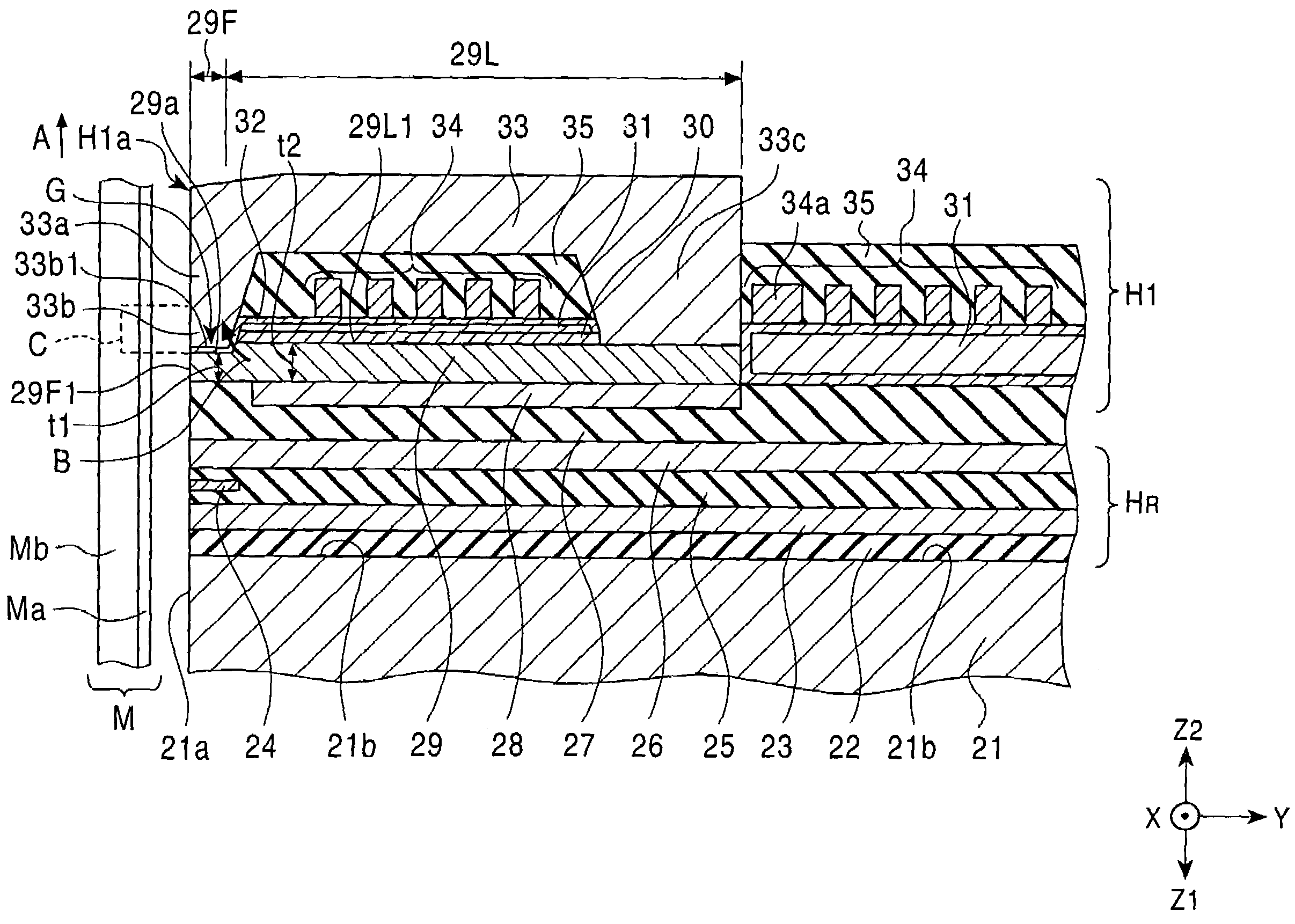
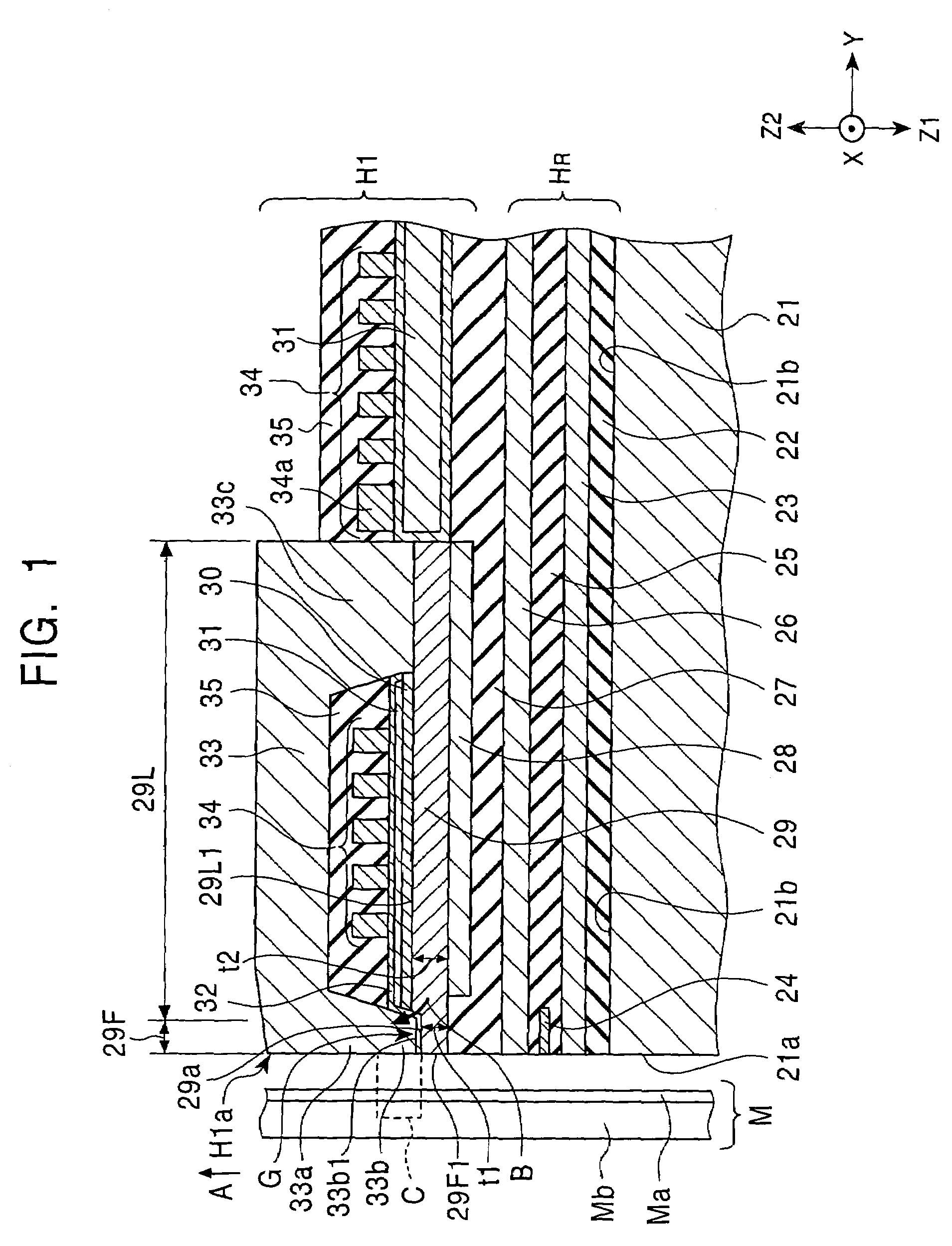
[0075]FIG. 1 is a cross-sectional view showing a perpendicular magnetic recording head of the present invention. A perpendicular magnetic recording head H1 shown in FIG. 1 is a magnetic head which applies a perpendicular magnetic field to a recording medium M to magnetize a hard film Ma thereof in a direction perpendicular thereto.

[0076]The recording medium M generally has a disc shape and is composed of a hard film Ma which has a high residual magnetization and is provided at a side facing the magnetic head, and a soft film Mb which has a high magnetic permeability and is provided behind the hard film Ma. The disc is rotated around the center thereof.

[0077]A slider 21 is formed of a non-magnetic material such as Al2O3.TiC, and a facing surface 21a of the slider 21 faces the recording medium M. When the recording medium M is rotated, by an airflow along the surface thereof, the slider 21 is allowed to float from a surface of the recording medium M, or the slider 21 is allowed to sli...

second embodiment

[0148]FIG. 7 is a vertical cross-sectional view of a perpendicular magnetic recording head of the present invention. The difference of the perpendicular magnetic recording head shown in FIG. 7 from that shown in FIG. 1 is that the second non-magnetic layer 30 is not formed. In this embodiment, the structures and the materials of the constituent elements having the same reference numerals are the same as those described in FIGS. 1 and 2, unless otherwise stated.

[0149]Also in this embodiment, the main magnetic pole layer 29 has the front portion 29F having a small film thickness t1 at the facing surface H1a side and the rear portion 29L having a large film thickness t2 at the rear side in the height direction. The front end surface 29F1 of the front portion 29F at the facing surface H1a side is exposed at the facing surface H1a.

[0150]FIG. 8 is a front view of the magnetic head shown in FIG. 7. FIG. 7 is a cross-sectional view showing the magnetic head which is taken on the chain line...


PUM

PropertyMeasurementUnit
thicknessaaaaaaaaaa
widthaaaaaaaaaa
non-magneticaaaaaaaaaa

Abstract

In a non-magnetic material layer, a concave portion is formed above a groove G. In addition, an auxiliary magnetic pole layer is formed having a convex portion which extends in the direction toward a main magnetic pole layer and which is placed in the concave portion. Accordingly, since a magnetic flux B passing in a perpendicular magnetic recording head from the main magnetic pole layer to the auxiliary magnetic pole layer is generated, an appropriate adjustment of the intensity of a magnetic field A generated from the main magnetic pole layer can be easily performed, and the edge of a recording track on a recording medium M can be clearly defined.

Description

[0001]This application claims the benefit of priority to Japanese Patent Application No. 2003-396976, herein incorporated by reference.BACKGROUND OF THE INVENTION[0002]1. Field of the Invention[0003]The present invention relates to perpendicular magnetic recording heads for performing recording by applying a magnetic field perpendicularly to a surface of a recording medium such as a disc, and more particularly, relates to a perpendicular magnetic recording head capable of recording magnetic data on a recording medium with narrow track pitches and a method for manufacturing the same.[0004]2. Description of the Related Art[0005]A magnetic head shown in FIG. 13 is a recording magnetic head used for a perpendicular magnetic recording device. The perpendicular magnetic recording device in which a recording medium is magnetized in a direction perpendicular to the surface thereof is able to record magnetic data at a high density as compare to a device in which a recording medium is magneti...

Claims


Application Information

Patent Timeline
Patent Type & Authority Patents(United States)
IPC IPC(8): G11B5/147G11B5/187G11B5/11G11B5/31G11B5/127
CPCG11B5/1278
Inventor YAZAWA, HISAYUKIKOBAYASHI, KIYOSHI
Owner TDK CORPARATION
Why Eureka
Try Eureka