Conveying duct pressure monitor system for controlling harvester speed

a technology of duct pressure monitor and harvester speed, which is applied in the field of air duct system for harvester, can solve the problems of present vacuum monitoring system, affecting the overall machine capacity of cotton, and requiring trial and error, so as to reduce the incidence of machine overload or under-capacity operation, maintain peak machine productivity, and facilitate calibration

Active Publication Date: 2007-07-31
DEERE & CO
View PDF23 Cites 15 Cited by
  • Summary
  • Abstract
  • Description
  • Claims
  • Application Information

AI Technical Summary

Benefits of technology

[0006]It is another object of the present invention to provide an improved system for monitoring a harvester air duct system which is reliable, easy to calibrate and unaffected by changes in air pressure in the cab of the harvester. It is yet a further object to provide such a system which helps the harvester operator maintain peak machine productivity and reduces incidences of the machine overload or under-capacity operation.
[0009]The system is not affected by the variation in cab pressure. Therefore, need for resetting is reduced or eliminated, or achieved automatically. Additionally, the system continuously identifies duct vacuum, which will allow the operator or an automatic speed control system to adjust vehicle ground speed to optimize performance. Loading on a crop processor structure is also monitored to provide a load indication which is used to control harvester ground speed. The system allows an inexperienced person to operate the machine near maximum capacity without plugging and relieves operator stress by automatically controlling the ground speed. The operator does not have to watch the cleaner speed and vacuum as closely and has more time to monitor and control other machine functions.

Problems solved by technology

If the harvester is a cotton stripper equipped with a cotton cleaner, the capacity of the cleaner to process and remove the burs and foreign material from the cotton also affects the overall machine capacity.
Several problems exist with present vacuum monitoring systems.
Secondly, setting the sensor requires a trial and error approach wherein the operator increases speed until the machine plugs to see if the sensor is set correctly.
The third problem with the current vacuum system is inability of such a system to inform the operator when there is additional capacity available in the air system.
As a result, machine productivity is compromised.

Method used


Image

  • Conveying duct pressure monitor system for controlling harvester speed
  • Conveying duct pressure monitor system for controlling harvester speed

Examples


Embodiment Construction

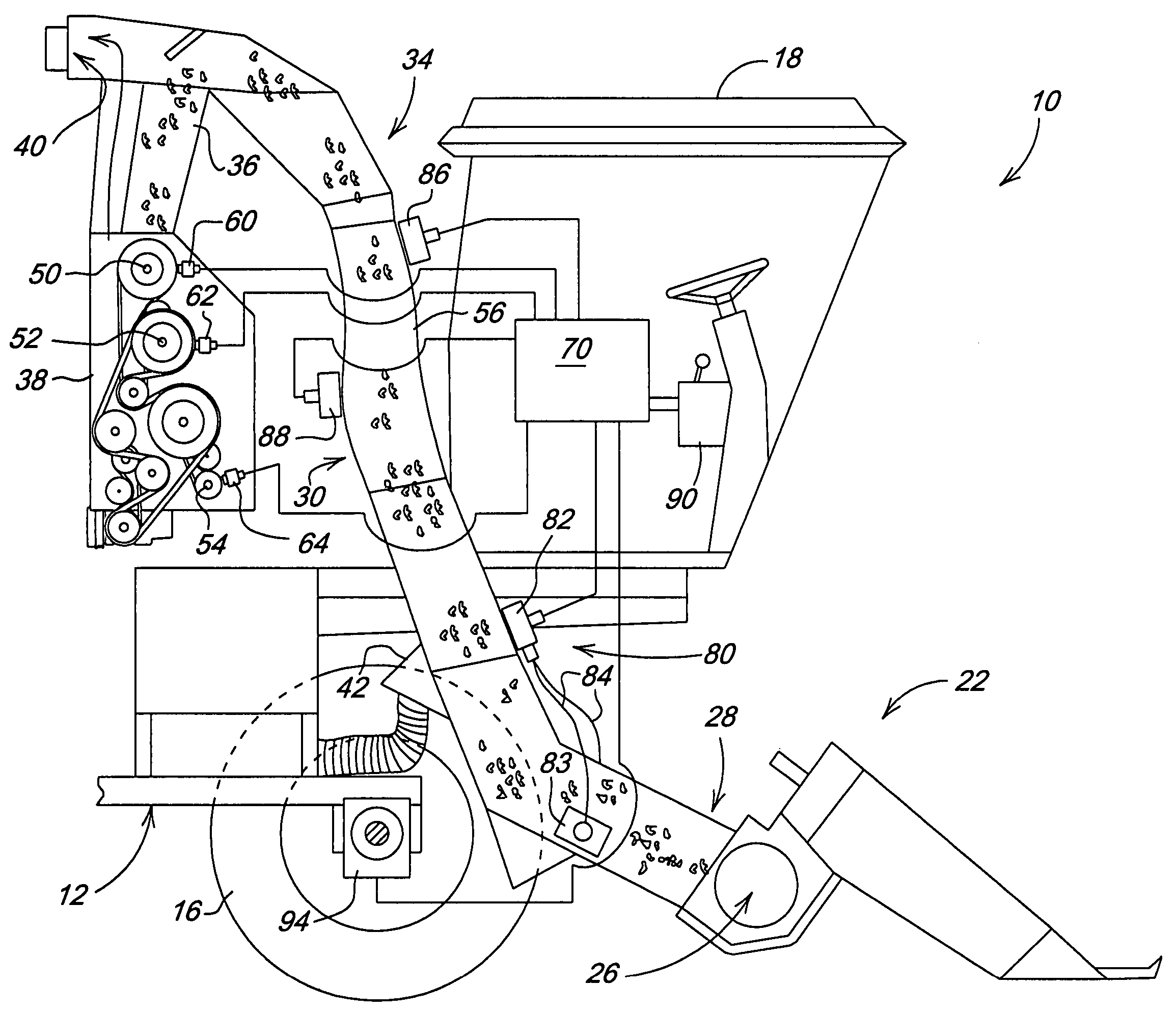
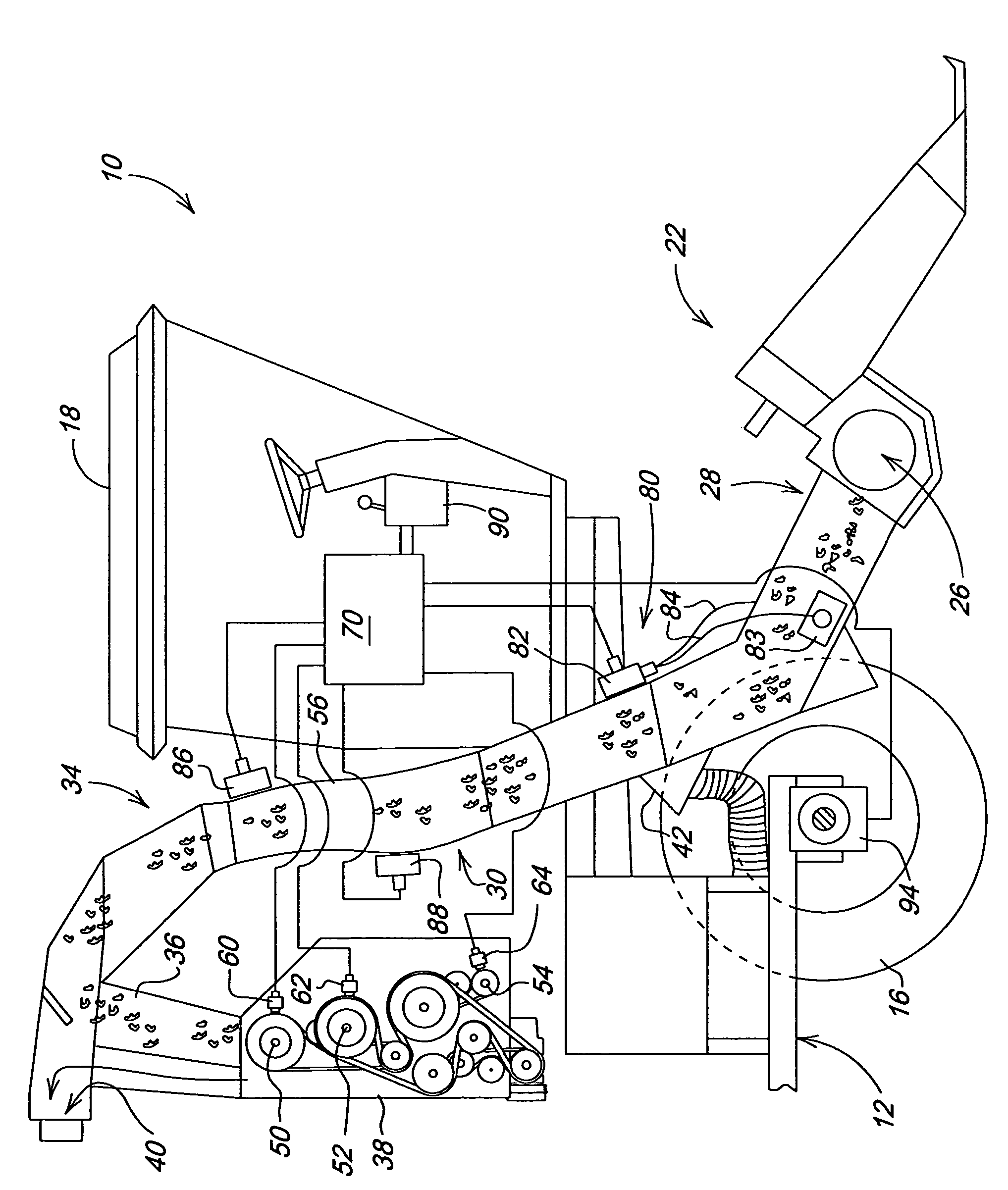
[0012]Referring now to FIG. 1, therein is shown a cotton harvester 10 having a main frame 12 supported for forward movement over the ground by forward drive wheels 16 and rear steerable wheels (not shown). A cab 18 is supported on the forward end of the frame 12. A lift frame is adjustably supported from the forward end of the frame 12 for mounting a conventional header 22 for stripping cotton material from rows of cotton plants. The header 22 includes a cross auger 26 for conveying stripped cotton and other material to a central outlet location which opens rearwardly into a separation duct 28.

[0013]Air duct structure 30 with an S-shaped configuration curves upwardly and rearwardly from the separation duct 28 to an upper separation grate area structure 34 which selectively directs conveyed material downwardly through an input duct 36 to an on-board processor such as a cotton cleaner 38 as shown in FIG. 1, or rearwardly to a basket or receptacle through an outlet area 40. The grate a...


PUM


Abstract

A differential pressure sensor measures the vacuum in a material conveying duct relative to atmospheric pressure or to a positive pressure farther upstream in the duct on an agricultural harvester. The output from this sensor is monitored electronically, and the resulting output is used to optimize harvester speed. In one embodiment, a processor monitor output is used in conjunction with the pressure sensor output to control ground speed. Processor speed or loading and air duct pressure are monitored to determine which area of the machine is the limiting factor and to adjust the harvester speed accordingly.

Description

FIELD OF THE INVENTION[0001]The present invention relates generally to an agricultural harvester having an air duct system to convey harvested material and, more specifically, to a device for controlling harvester speed dependent on the pressure in the duct system.BACKGROUND OF THE INVENTION[0002]The harvesting capacity of a cotton harvester is determined by the capacity of the harvesting unit to remove the cotton from the plant and the capacity of the air system to convey the cotton downstream from the harvesting unit. If the harvester is a cotton stripper equipped with a cotton cleaner, the capacity of the cleaner to process and remove the burs and foreign material from the cotton also affects the overall machine capacity.[0003]The operator can see when the row units are operating at or above capacity by the amount of cotton left on the stalk, and in over-speed conditions, excess cotton will remain. However, a monitor system is required for the operator to determine if the air sys...

Claims


Application Information

Patent Timeline
Patent Type & Authority Patents(United States)
IPC IPC(8): A01D46/08
CPCA01D46/085
Inventor GOERING, KEVIN JACOBFERREE, PHILIP EUGENEDZUBAK, ALAN LEE
Owner DEERE & CO
Why Eureka
Try Eureka