Pressure transmitter with power cycled hall effect sensor

a transmitter and hall effect technology, applied in fluid pressure measurement using inductance variation, instruments, roads, etc., can solve the problems of not enough power left, most hall effect devices available today consume more power than 40 mw, and not enough power to run the hall effect sensor itsel

Active Publication Date: 2007-07-31
DWYER INSTR
View PDF12 Cites 21 Cited by
  • Summary
  • Abstract
  • Description
  • Claims
  • Application Information

AI Technical Summary

Benefits of technology

[0006]The use of a Hall effect sensor and a magnet allows for physical separation of the mechanical and electrical components of the pressure transducer, since the interaction between the magnet and the Hall effect sensor can take place with material between them. The preferred embodiment shows an arrangement where the fluid in the differential pressure sensor and the mechanical beam and magnet are separated from the electronics, including the Hall effect sensor, by a wall.

Problems solved by technology

A problem arises in that most Hall effect devices available today consume more power than 40 mW.
With such power requirements, not only is there no power left over to run the rest of the transmitter, there is not enough power to run the Hall effect sensor itself.
While other ranges are possible, the limitations of the average current draw and surge current to the sensor still must be achieved.

Method used


Image

  • Pressure transmitter with power cycled hall effect sensor
  • Pressure transmitter with power cycled hall effect sensor
  • Pressure transmitter with power cycled hall effect sensor

Examples


Embodiment Construction

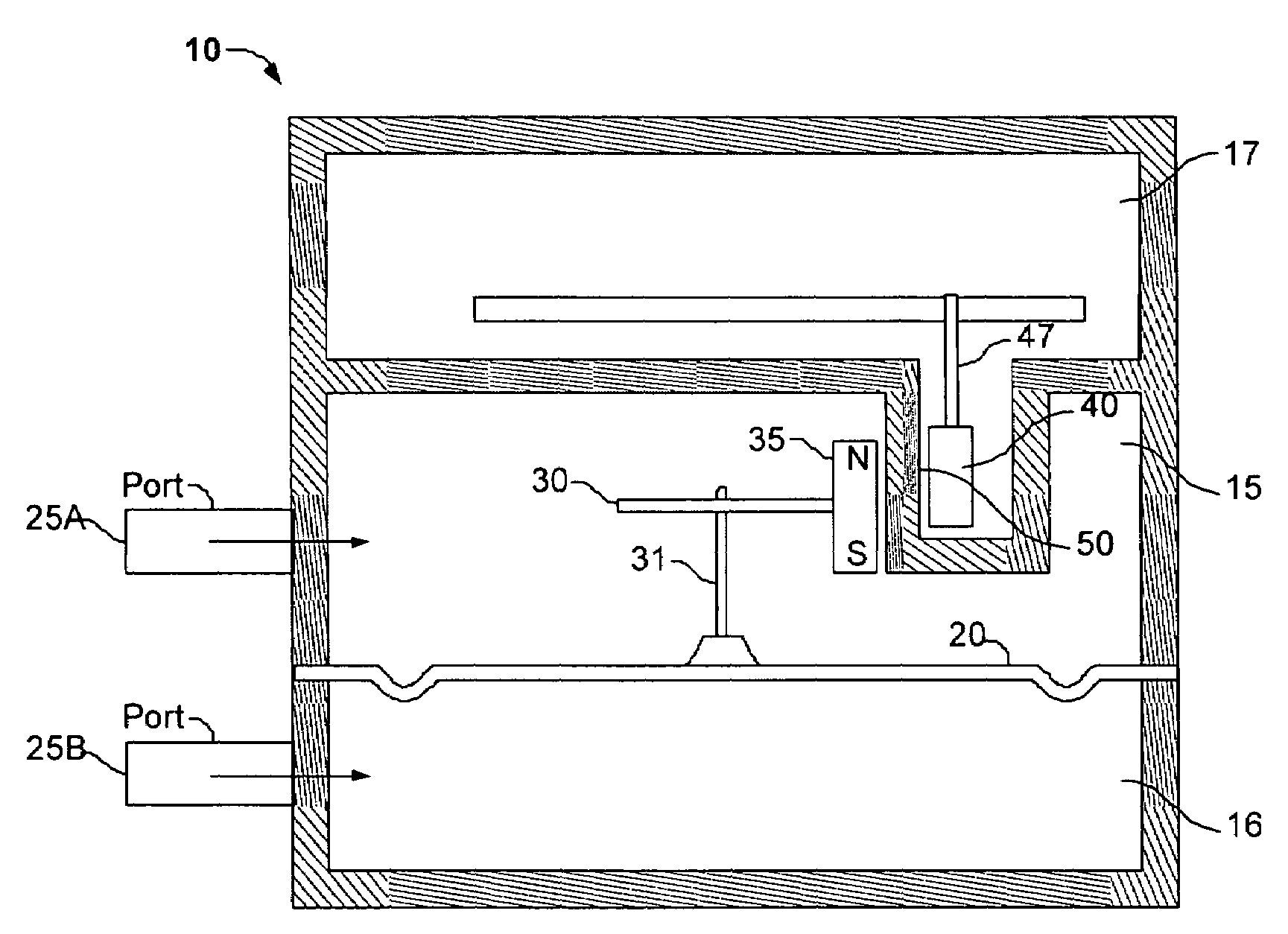
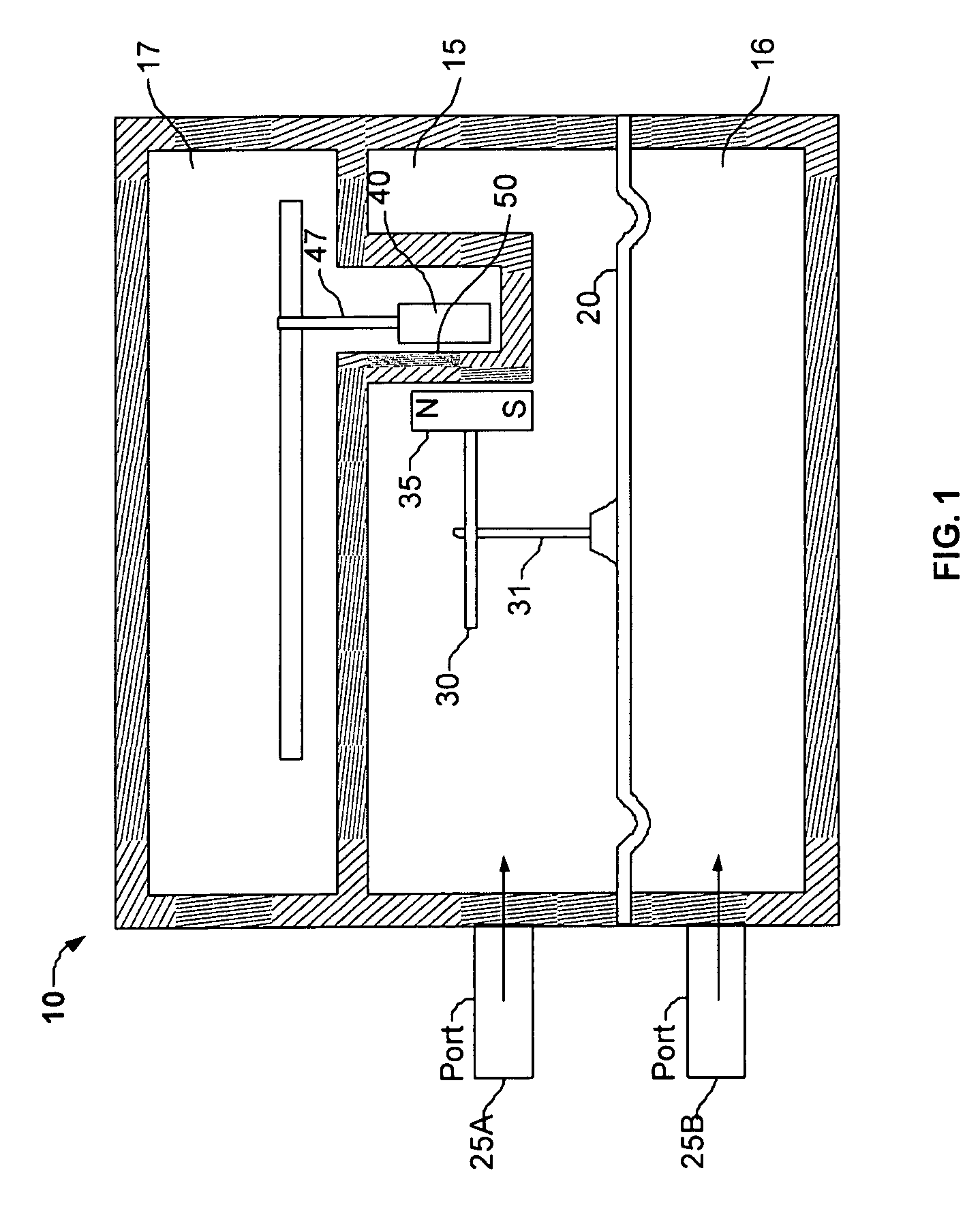
[0015]With reference to FIG. 1, the pressure transducer 10 includes three isolated chambers or plenums, an upper pressure chamber 15 above the diaphragm 20, a lower pressure chamber 16 below the diaphragm 20, and a separate electronics chamber 17 above the upper pressure chamber 15. A flexible diaphragm 20 separates the upper and lower chambers. The upper chamber 15 and the lower chamber 16 include ports 25A and 25B to allow fluid communication with the plenums defined by their respective walls. The upper chamber 15 includes a beam 30 affixed to the diaphragm 20. The beam 30 is coupled to and moves in conjoined relationship with the diaphragm 20. In the preferred embodiment, the beam 30 is coupled to the diaphragm 20 by a post 31 extending perpendicularly from the diaphragm 20. A magnet 35 is attached to one end of the beam 30. The beam 30 is attached to the post 31, so that the beam 30 and magnet 35 are generally balanced about the post 31, so as to minimize any twisting forces on ...


PUM

PropertyMeasurementUnit
supply voltageaaaaaaaaaa
poweraaaaaaaaaa

Abstract

The invention disclosed herein is a pressure transducer utilizing a Hall effect sensor to detect the displacement of the transducer's diaphragm. The pressure transducer includes a power supply to draw current from a 4 mA to 20 mA current loop and deliver current to the Hall effect sensor at an average rate of 4 mA or less.

Description

RELATED APPLICATIONS[0001]This Application claims the benefit of U.S. Provisional Application No. 60 / 541,136, filed on Feb. 2, 2004.FIELD OF THE INVENTION[0002]The invention relates to differential pressure transducers and transmitters for measuring the pressure of a fluid.BACKGROUND OF THE INVENTION[0003]The invention described herein is a pressure transducer utilizing a magnet and Hall effect sensor to convert mechanical movement into electrical signals. The pressure transducer without a Hall effect sensor is well understood in the art. A pressure transducer typically includes two plenums or chambers separated by a flexible diaphragm. The plenums are subject to a fluid, such as a gas or a liquid, under different pressures. This pressure differential causes displacement of the diaphragm in the direction of the plenum exposed to the lower pressure. The diaphragm is connected to a mechanical component, which moves as the diaphragm is displaced.[0004]For example, the mechanical compon...

Claims


Application Information

Patent Timeline
Patent Type & Authority Patents(United States)
IPC IPC(8): G01L9/10G01L7/08G01L9/00
CPCG01L9/007E01C11/222E01C5/005E01C2201/06E01C2201/16
Inventor HEUER, DANIEL A.EDWARDS, SHANNON
Owner DWYER INSTR
Why Eureka
Try Eureka