Cutting machine

a cutting machine and cutting head technology, applied in the field of cutting head machines, can solve the problems of not being able to be directly controlled or observed, the entire apparatus must be removed from the pipe, and the removal of the entire apparatus is not often easy, and achieves the effect of high speed

Inactive Publication Date: 2007-07-31
BOWMAN THOMAS W
View PDF33 Cites 25 Cited by
  • Summary
  • Abstract
  • Description
  • Claims
  • Application Information

AI Technical Summary

Benefits of technology

[0009]In accordance with another feature of the invention, the ram and rotate/feed assembly is constructed so that the tool can be simultaneously rotat

Problems solved by technology

Because the reinstatement cutting machine is moved along the liner of the main, it cannot be directly controlled or observed.
Otherwise, the entire apparatus must be removed from the pipe, which is not often easy, as a cutter may fail or the mobility of the cutting machine may be lost, while the bit is extended radially into the

Method used


Image

  • Cutting machine
  • Cutting machine
  • Cutting machine

Examples


Embodiment Construction

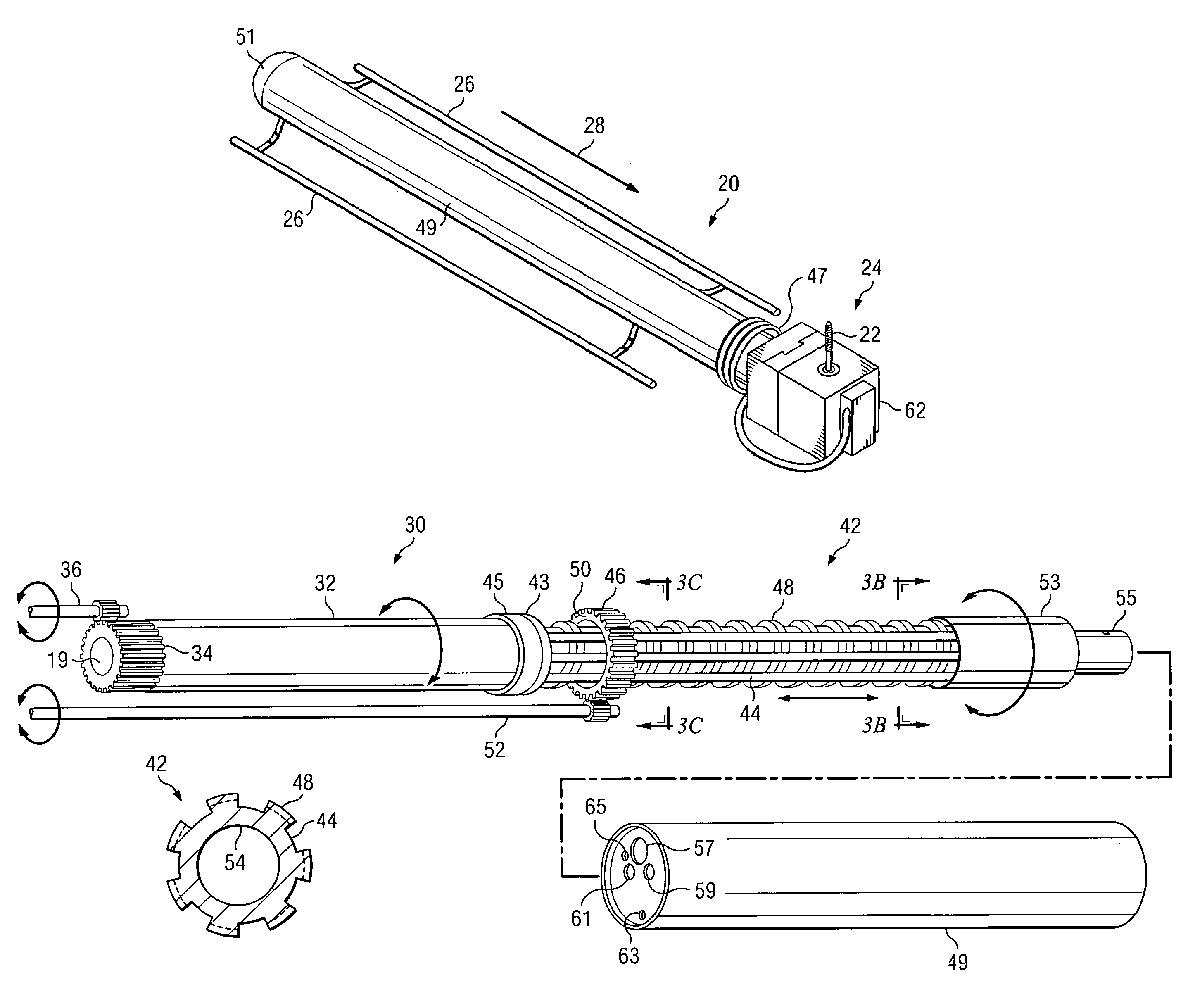
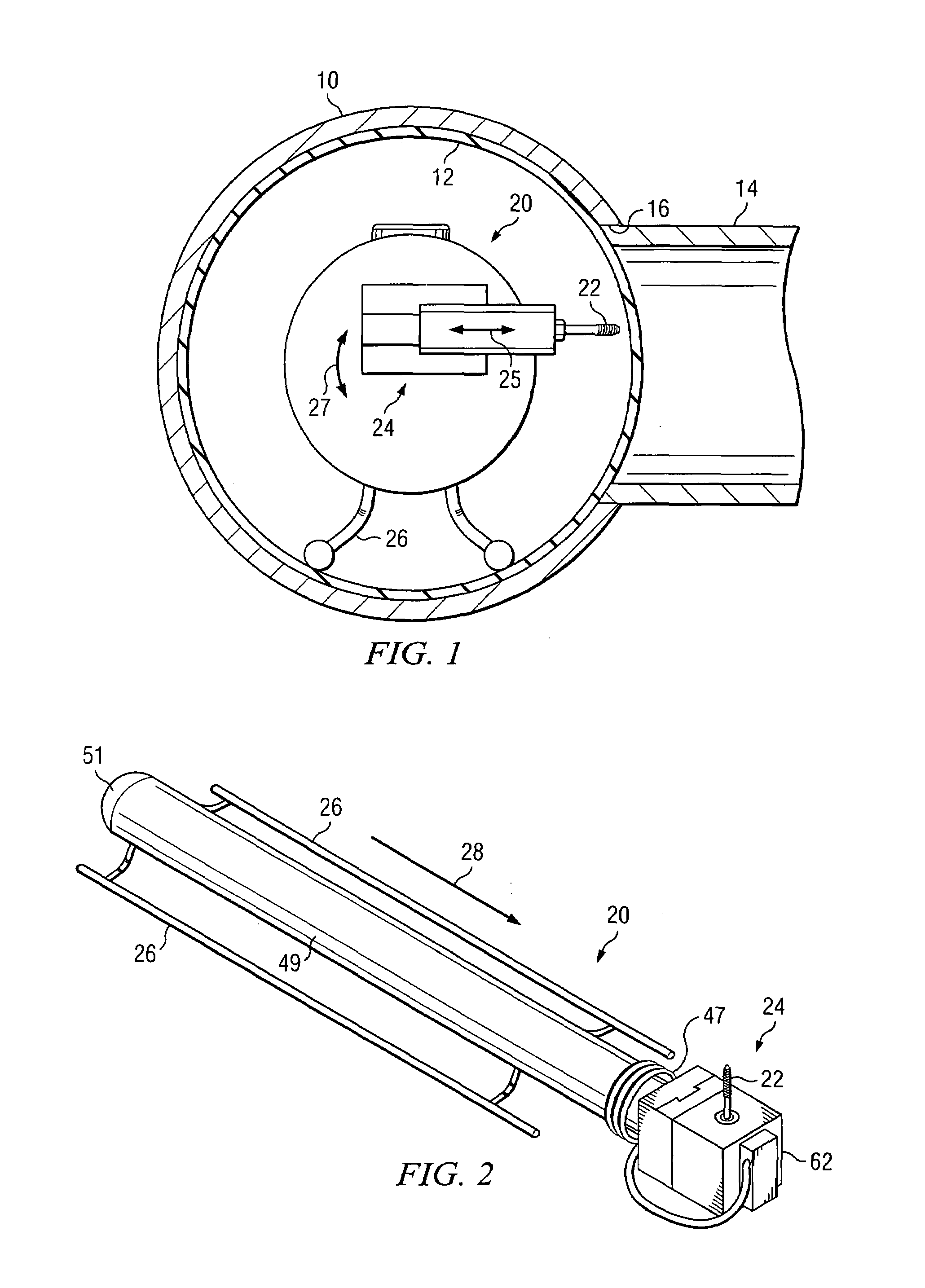
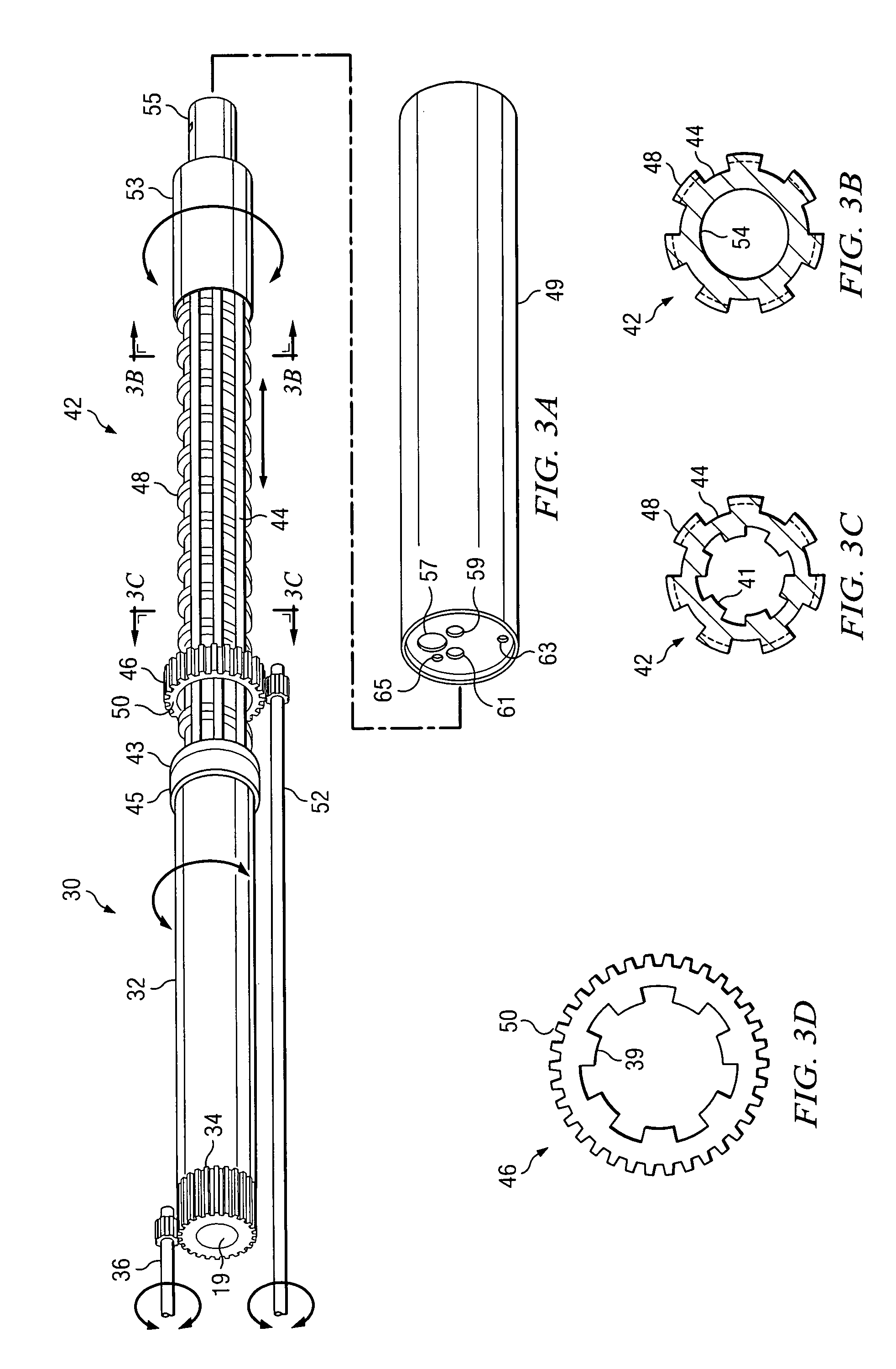
[0028]With reference to FIG. 1, there is shown an underground main 10 that has been retrofitted with a plastic sleeve or liner 12. The manner in which plastic sleeves 12 are installed in broken or deteriorated mains is well known in the art. Connected to the main 10 is a lateral pipe 14. The main 10 has an opening 16 therein in alignment with the lateral 14 so that the liquid can flow from the lateral 14 to the main 10. When the plastic sleeve 12 is cured in place in the main 10, the opening 16 is closed and must be reinstated by a cutting machine 20. The reinstatement cutting machine 20 is equipped with a bit 22 or other type of cutting device that is adapted for cutting the plastic material of the sleeve 12. The bit 22 is rotated by an air-driven motor, and is moved in a circular path by various movements imparted to the cross slide assembly 24 that holds the bit 22. As will be described below, the bit 22 is moved radially inwardly and outwardly by a male and female dove-tail slid...


PUM


Abstract

Cutting apparatus having a ram axis gear tube (32) equipped with internal threads engageable with external threads (48) of a main shaft (42). A tool can be fixed to the main shaft (42). The external threads (48) of the main shaft (42) are formed on external splines (44). A main shaft rotation gear (46) has internal splines (41) mating with the external splines (44) of the main shaft (42). Rotation of the ram axis gear tube 32 thus causes the main shaft (42) to move axially via the internal and external threads. Rotation of the main shaft rotation gear (46) causes rotation of the main shaft (42). The tool fixed to the main shaft (42) can thus undergo axial and rotational movements. A motor (74) can be coupled to main shaft (42) and a motor shaft (63) extended through the ram axis gear tube (32) and the main shaft (42). The motor shaft (63) can drive a linear gear (68) of a cross slide assembly (24) and thus radially move a tool fixed to the cross slide assembly (24).

Description

RELATED APPLICATION[0001]This non-provisional patent application claims the benefit of pending provisional application entitled “Cutting Machine,” filed Feb. 23, 2005 and accorded Ser. No. 60 / 655,704, the entire disclosure of which is incorporated herein by reference.TECHNICAL FIELD OF THE INVENTION[0002]The present invention relates in general to machine tools, and more particularly to a cutting machine that has a cutter mounted to a rotating shaft, where the shaft moves longitudinally.BACKGROUND OF THE INVENTION[0003]Many different types of cutting tools are available for use in a variety of applications. In most industrial situations, either the cutter is rotated or otherwise moved, and the workpiece is maintained stationary. In other situations, the cutter is stationary and the workpiece is rotated or otherwise moved. In yet other applications, both the cutter and the workpiece may be moved at the same time.[0004]Reinstatement cutting machines are special applications where a cu...

Claims


Application Information

Patent Timeline
IPC IPC(8): B23C3/00
CPCB23C1/20B23Q5/40B23Q1/489Y10T74/18664Y10T409/307056Y10T74/1864Y10T409/309352Y10T74/18624Y10T408/6771Y10T409/303808Y10T408/6793Y10T409/308232Y10T74/18696Y10T409/306776Y10T409/304424Y10T74/18632Y10T74/18704
Inventor BOWMAN, THOMAS W.
Owner BOWMAN THOMAS W
Why Eureka
Try Eureka