Heating cable guide strip for electric radiant floor heating and method of use

Active Publication Date: 2007-07-31
FLEXTHERM
View PDF12 Cites 55 Cited by
  • Summary
  • Abstract
  • Description
  • Claims
  • Application Information

AI Technical Summary

Benefits of technology

[0006]Another feature of the present invention is to provide a heating cable guide strip which permits the installation of resistance heating cables along different configurations to adapt to floor areas of varying shapes and which permits the cable to be installed in wire runs of different spacings in

Problems solved by technology

There are several disadvantages with known systems and a main one is the time required to install the cable.
The cementitious slurries may shrink and crack during its curing cycle and thus tends to disrupt the heating cable which could cause a rupture

Method used


Image

  • Heating cable guide strip for electric radiant floor heating and method of use
  • Heating cable guide strip for electric radiant floor heating and method of use
  • Heating cable guide strip for electric radiant floor heating and method of use

Examples


Embodiment Construction

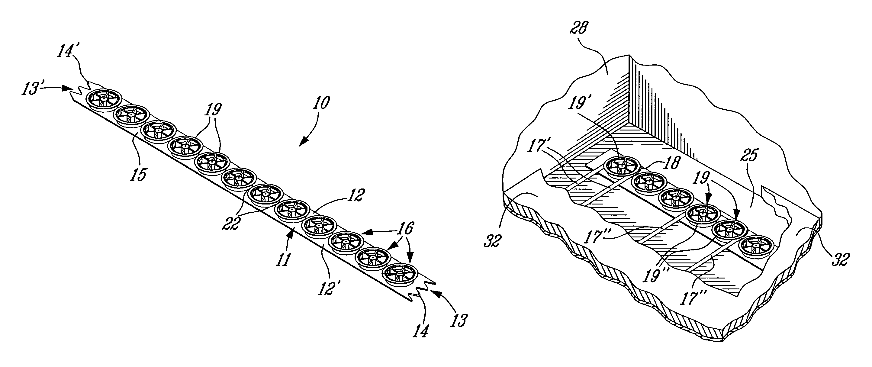
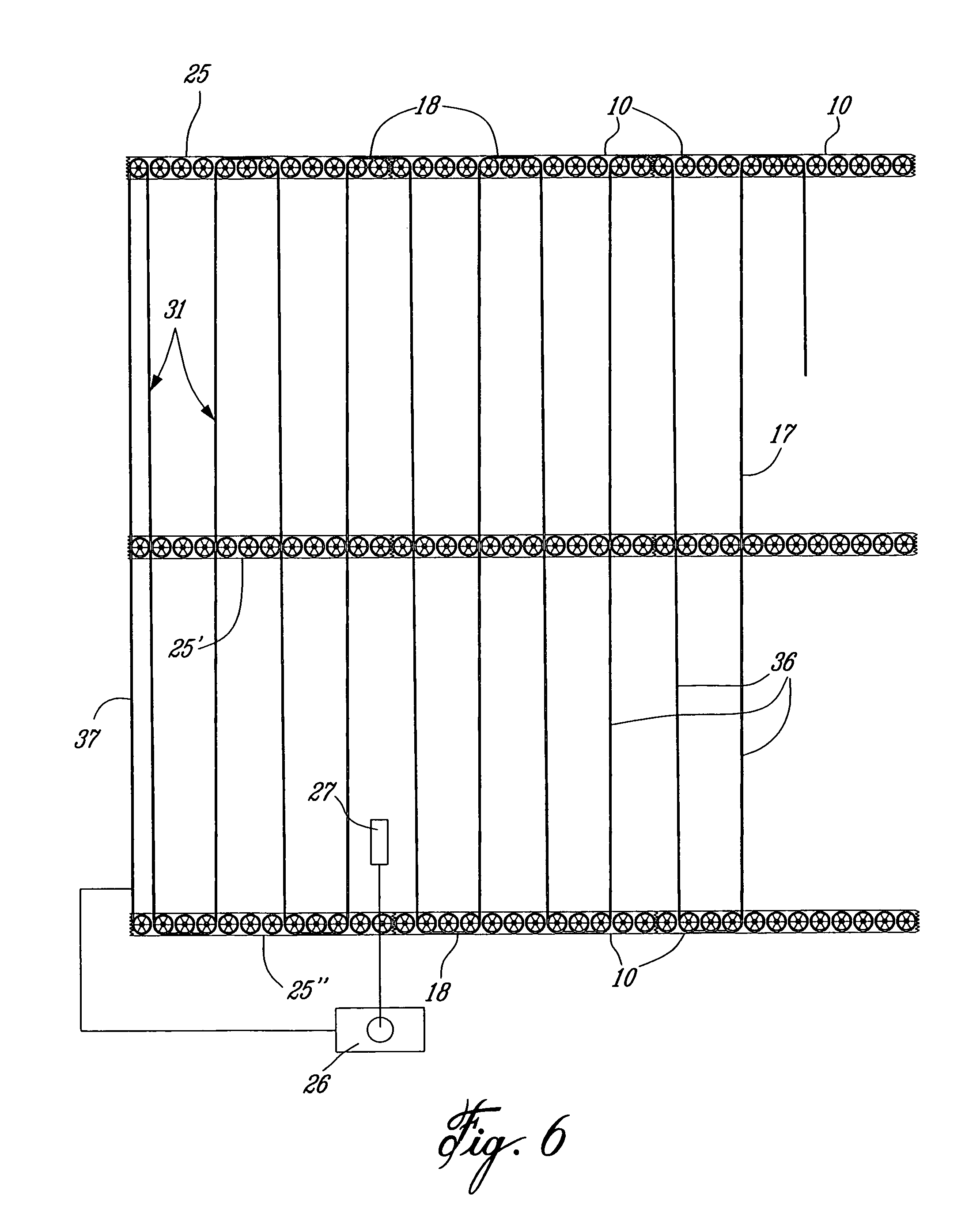
[0021]Referring now to the drawings and more particularly to FIGS. 1 to 4, there is shown generally at 10 the heating cable guide strip of the present invention. This guide strip is injected molded out of plastics material and is formed in lengths of approximately 12 inches although these can be shorter or longer and the length thereof is therefore not an essential feature of the present invention. As hereinshown the wire guide strip 10 defines an elongated flat base 11 of rectangular cross-section defining opposed parallel elongated edges 12 and 12′ and end edges 13 and 13′. The end edges 13 and 13′ are provided with inter-engaging alignment means in the form of wave-shaped formations 14 and 14′ whereby two or more of these heating cable guide strips 10 can be inter-engaged in straight alignment end-to-end (see FIG. 6).

[0022]Projecting above a top surface 15 of the flat base 11 are a plurality of spaced-apart wire retaining guide members 16 for retaining and guiding a heating cable...


PUM

PropertyMeasurementUnit
Flexibilityaaaaaaaaaa
Shapeaaaaaaaaaa

Abstract

A heating cable guide strip for retaining and guiding a resistance heating cable in a serpentine path on a sub-floor adapted to receive a cementitious material to form a radiant heated floor is described. The method of use is also described. The heating cable guide strip is molded of plastics material and defines an elongated flat base having a plurality of spaced-apart wire retaining guide members. The retaining guide members have at least a curved section for guiding the heating cable along a curved path about one or more of the guide members. The guide members further have a flexible cable retention flange to permit the positioning and retention of the cable captive between opposed ones of the retaining guide members. The heating cable guide strip is attached to the sub-floor by glue, nails or screws.

Description

TECHNICAL FIELD[0001]The present invention relates to a heating cable guide strip for retaining and guiding a resistance heating cable in a serpentine path over a sub-floor adapted to receive a cementitious material whereby to embed the resistance heating cable to form a radiant floor heating system.BACKGROUND ART[0002]Electric radiant floor heating systems are known and a typical one of these systems is described in U.S. Pat. No. 4,878,332 issued on Nov. 7, 1989 to Infloor Inc. These systems comprise a plurality of cable retaining strips which are secured to a sub-floor surface whereby to support a resistance heating cable along a serpentine path and spaced above the top surface of the sub-floor. Once the cable is installed, a cementitious slurry is then poured over the sub-floor whereby to embed the resistance heating cable into the cement layer. Resistance heating cables are today covered with a suitable insulation material whereby to protect the resistive wire and therefore the ...

Claims


Application Information

Patent Timeline
IPC IPC(8): H02G9/00
CPCF24D3/141H05B3/06Y02B30/00
Inventor MORAND, MICHELCHARRON, PHILIPPE
Owner FLEXTHERM
Why Eureka
Try Eureka