Method and apparatus for generating pulse-width modulated waveform
a pulse-width modulated waveform and generator technology, applied in the direction of pulse technique, motor/generator/converter stopper, dynamo-electric converter control, etc., can solve the problem of increasing the time that both power transistors of the upper and lower arms are kept off, difficult to achieve optimal complementary switching, and inability to individually and controllably set the dead time at each of the upper and lower arms. , to achieve the effect of saving energy, increasing the total torque,
- Summary
- Abstract
- Description
- Claims
- Application Information
AI Technical Summary
Benefits of technology
Problems solved by technology
Method used
Image

Examples
first embodiment
[First Embodiment]
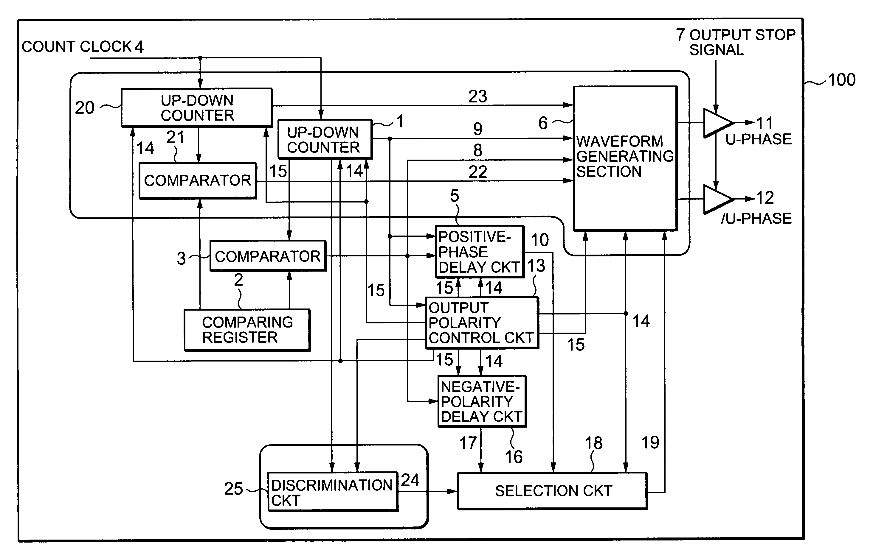
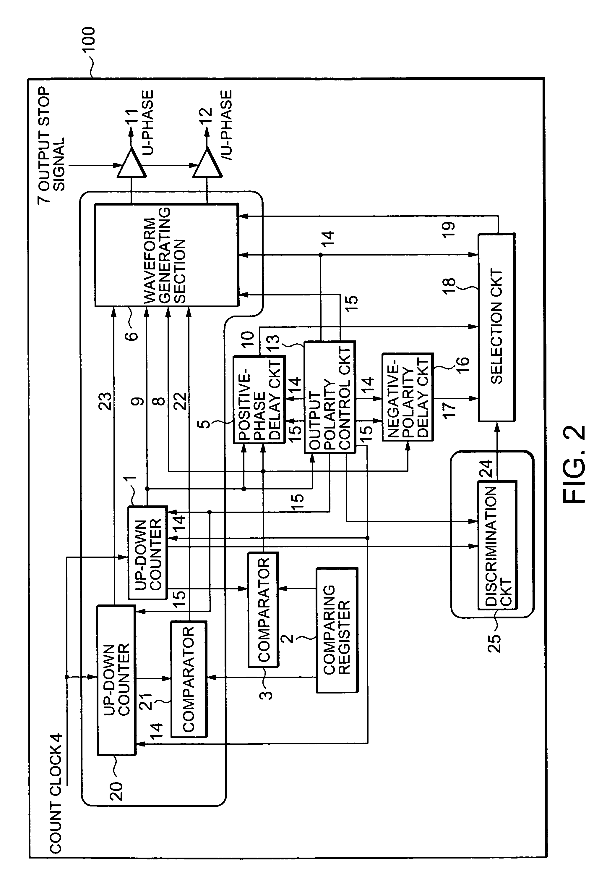
[0052]A three-phase PWM waveform generator 100 according to a first embodiment of the invention will be described with reference to FIG. 2. The three-phase PWM waveform generator 100 includes an up-down counter 1, a comparing register 2, a comparator 3, a positive-phase delay circuit 5, a waveform generating section 6, an output-polarity control circuit 13 a negative-phase delay circuit 16, a selection circuit 18, an up-down counter 20, a comparator 21, and a discrimination circuit 25.
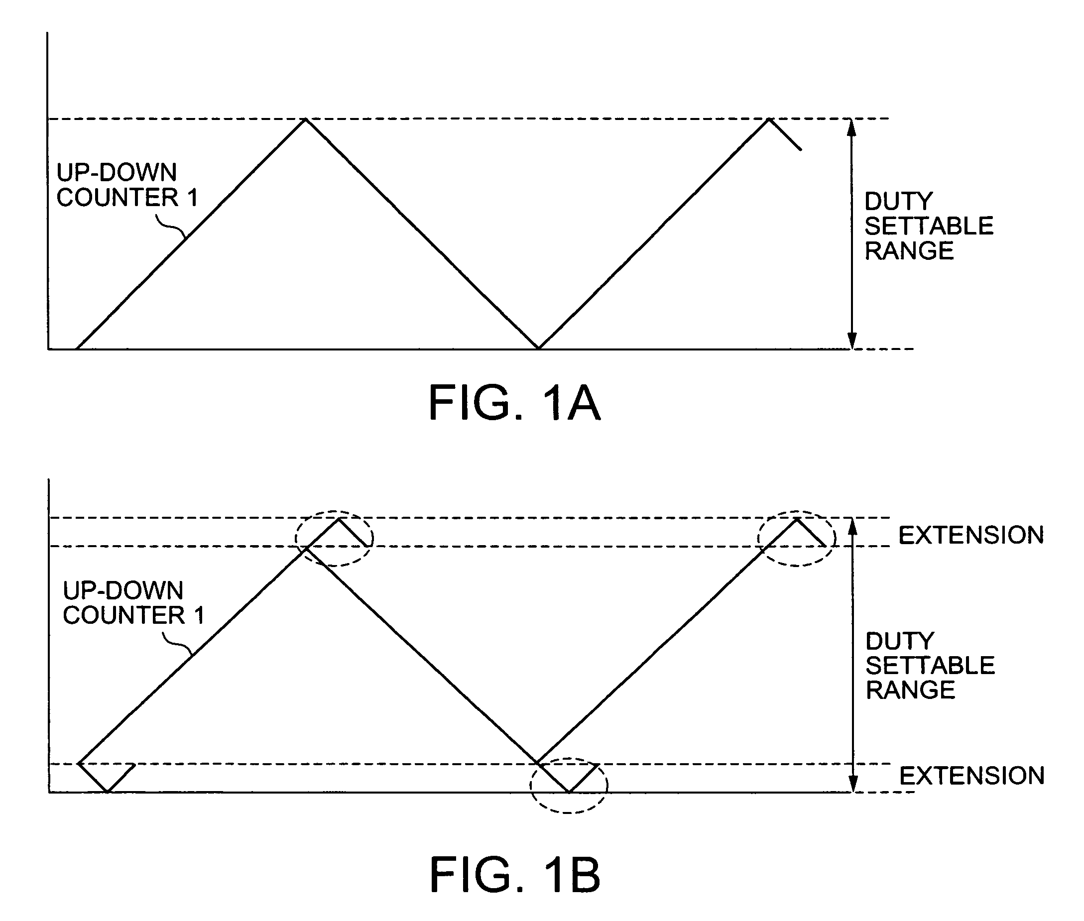
[0053]The up-down counter 1 is operated by a count clock 4 to perform an up-down counting operation, shown in FIG. 3, in the range from ((the set value of the positive-phase delay circuit 5) / 2) to ((the cycle of a carrier wave) / 2+(the set value of the positive-phase delay circuit 5) / 2). The up-down counter 1 outputs an alternate upward and downward triangular wave in a cycle of the carrier wave. The direction of the crest of the triangular wave is determined depending on the polarity ...
second embodiment
[Second Embodiment]
[0081]Referring to FIG. 7, a three-phase PWM waveform generator 200 according to a second embodiment of the invention will be described. The three-phase PWM waveform generator 200 includes a cycle register 31, dead-time registers 32 and 33, up-down counters 34, 35, and 36, a counter control circuit 37, a duty register 38, comparators 39 and 40, and a waveform generating section 41.
[0082]In the cycle register 31, the value of (the cycle of a carrier wave) / 2 is set.
[0083]To the dead-time register 32 (also referred to as a dead-time register 0), dead time (d0) at switching from positive phase OFF to negative phase ON is set.
[0084]To the dead-time register 33 (also referred to as a dead-time register 1), dead time (d1) at switching from negative phase OFF to positive phase ON is set.
[0085]The up-down counter 34 (also referred to as a counter 0) is a basic counter, which measures the cycle of the carrier wave. The counter 0 (34) counts up from d0 / 2 determined as the in...
PUM
 Abstract
Description
Claims
Application Information